TM 55-1925-282-14&P
0014 00
4
3
2
1
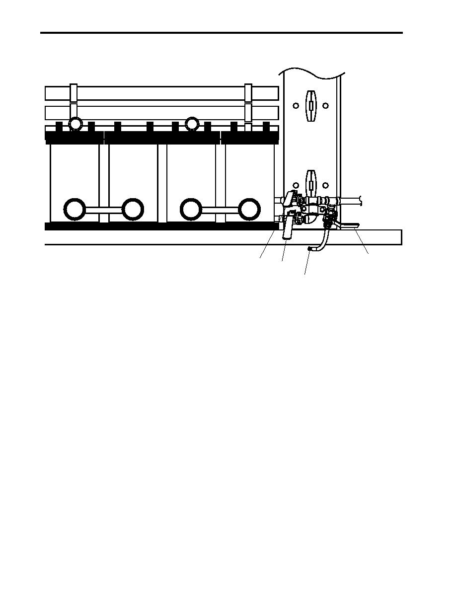
Figure 9. ROWPU Filter Inlet Valves
10. OPEN valves RO-V-1-1 (figure 9, item 2), RO-V-2-1 (figure 9, item 3), and RO-V-5 (figure 9, item 4).
11. CLOSE valves RO-V-1-2 (figure 8, item 3) and RO-V-2-2 (figure 8, item 4).
12. At both flow control panels, verify that the SYSTEM HIGH PRESSURE REGULATOR valves (figure 10,
item 1) are OPEN in the fully counterclockwise position.
13. At both system controllers, press the START switches (figure 11, item 1).
14. Verify that the SYSTEM ON indicators (figure 11, item 2) illuminate, and that both high pressure pumps start.
15. At both flow control panels, verify that the BRINE flow meters (figure 10, item 2) indicate flow rates of about
4 gallons (15 liters) per minute.
16. Allow the ROWPUs to recycle the cleaning solution for sixty minutes.
17. At both system controllers, press STOP (figure 11, item 3).
18. Verify that the high pressure pumps stop.
19. Disconnect all cleaning supply hoses from the ROWPU system piping.
20. Place antiseizing tape on the male pipe threads of the two plugs (figure 8, item 1 and 2), and install the plugs
in the cleaning supply piping.
0014 00-8

