
TM 55-1925-282-14&P
0024 00
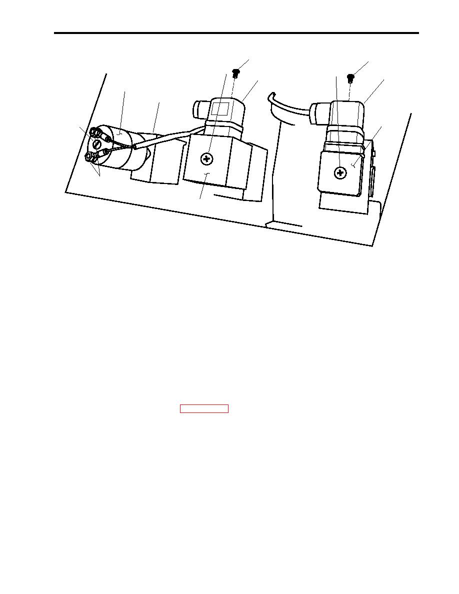
6
3
5
1
4
7
11
12
2
9
10
8
Figure 6. Flow Control Panel, Top View
e. Slowly CLOSE the SYSTEM HIGH PRESSURE REGULATOR (figure 4, item 8) until the SYSTEM OP-
ERATION PRESSURE gauge (figure 4, item 9) indicates between 900 PSI (62.1 bar) and 950 PSI (65.5
bar).
9. Press the STOP switch (figure 1, item 2).
10. Perform the Follow-On Service procedure at the end of this work package.
REPLACE HIGH PRESSURE CUTOFF SWITCH
REMOVAL
1. Shut down the applicable ROWPU (WP 0005 00).
2. At the 440V power panel No. 5, set to OFF, lock out, and tag out (FM 55-502) the applicable circuit breaker as
shown in table 1.
3. At the 24 Vdc control panel, set to OFF, lock out, and tag out (FM 55-502) the applicable circuit breaker as
shown in table 1.
4. CLOSE, lock out, and tag out (FM 55-502) the applicable inlet sea water supply valve as shown in table 1.
NOTE
Access to the high pressure cutoff switch is gained from the rear of the flow control
panel. It is not necessary to open the flow control panel to replace the switch.
5. Remove the screw (figure 6, item 3) that secures the wire plug (figure 6, item 4) to the high pressure cutoff
switch (figure 6, item 2).
0024 00-11
