
TM 55-1925-285-13&P
0002 00
LOCATION AND DESCRIPTION OF MAJOR COMPONENTS
1
3
2
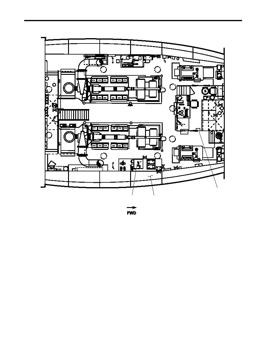
Figure 1. OCM and OWS Major Component Locations (Plan View)
1. OCM Remote Indicator (Alarm) Assembly (figure 1, item 1). This unit, located on the starboard bulkhead of
the EOS, is used to display OCM operating information, select the alarm limit (15/70 ppm) of the OCM, and
to provide audible and visual alarm indicators when the OCM system detects an unacceptable level of oil
content in the effluent.
2. Oily Waste Tank (figure 1, item 2). This tank provides storage for oily bilge water awaiting treatment by the
OWS. The tank also stores oil removed by the OWS. Oil and oily water that cannot be sufficiently cleansed
by the OWS are stored for discharge to a shore facility.
3. OWS Tank (figure 1, item 3). The OWS is located at frame 33, against the starboard bulkhead. The rectan-
gular, welded carbon steel tank is internally coated with coal tar epoxy, and externally painted with primer and
marine enamel. The internal components (baffle, weir, and coalescer boxes) are type II PVC plastic for
maximum corrosion resistance. There are no internal fasteners in the OWS tank. The coalescer boxes are
filled with special polypropylene granules (beads). To change the coalescer medium, these boxes can be
removed from the separator, emptied, refilled, and replaced. The OWS pump and OWS control panel are
mounted on the aft side of the OWS tank.
0002 00-2
