
0003 00
TM 55-1925-285-13&P
1
2
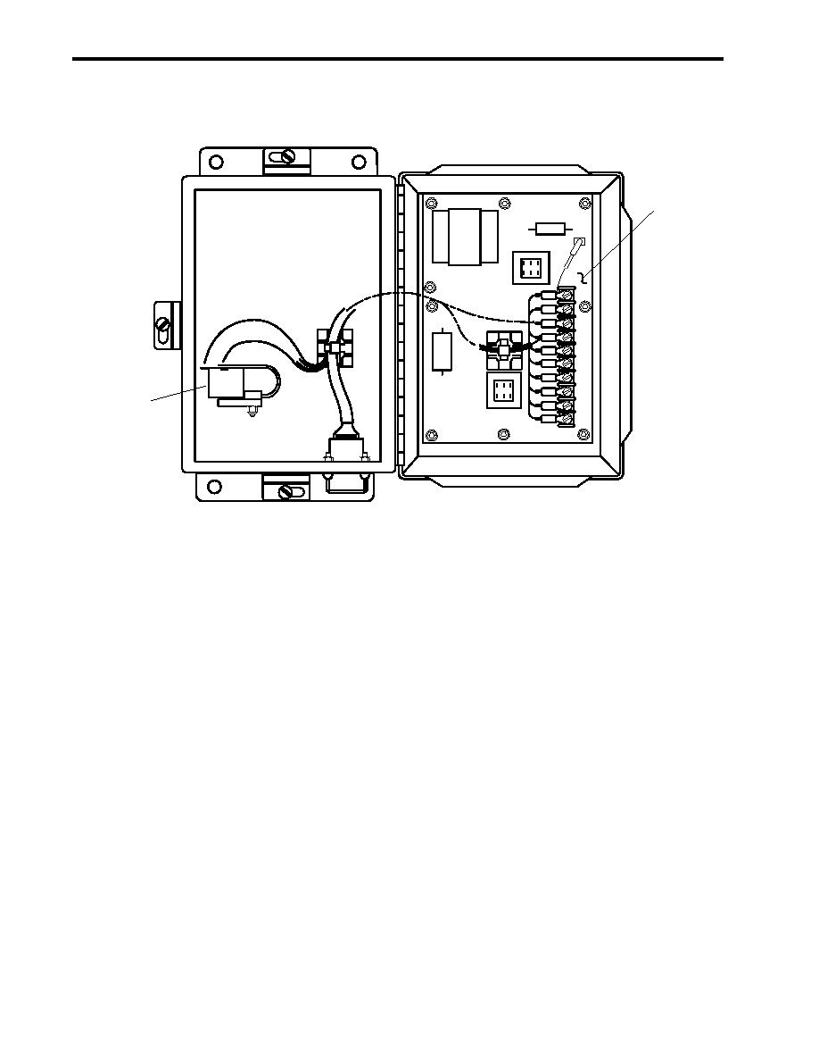
Figure 8. Remote Indicator (Alarm) Assembly, Internal
REMOTE RELAY ASSEMBLY
This assembly is the electrical control interface between the sampling/sensor assembly and the diverter solenoid
valve. The cable from the sampling/sensor assembly (A1P3) connects to receptacle A3P1 (figure 9, item 1) on
the bottom of the enclosure and provides alarm signals (120 Vac, single-phase, 60 Hz) for its operation. The
remote relay assembly contains the following components:
Timer (figure 9, item 2). The timer is a solid state component that provides a time delay (60-second) before the
alarm signal from the sampling/sensor assembly activates the two solid state relays. This time delay allows the
sampling/sensor assembly to verify that four consecutive samples have oil content below the selected alarm limit
before the diverter solenoid valve actuates, thereby preventing illegal overboard discharge and unnecessary
valve wear caused by frequent or sporadic alarm signals. Although this timer is adjustable, it should always be
set for a 60-second delay.
Solid State Relays (figure 9, items 3 and 4). Two solid state relays are contained in the remote relay assembly.
One relay is used to close the 120 Vac diverter solenoid valve circuit. After receiving an alarm signal from the
timer, this Normally Open (NO) relay closes after the 60-second delay described above. The other relay is a
spare, available for auxiliary use.
Terminal Strip (figure 9, item 5). This strip provides the electrical connection points between the relays and the
diverter solenoid valve circuit.
0003 00-10
