TM 55-1925-285-13&P
0003 00
3
4
5
5
4
4
R1
R2
1
3
1
3
1
2
3
4
TC
1
3
2
5
1
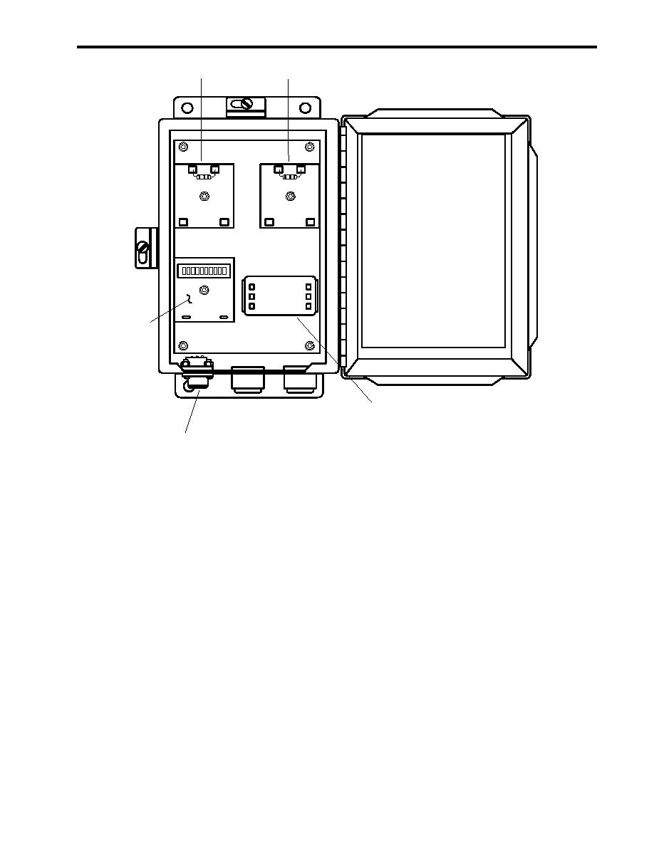
Figure 9. Remote Relay Assembly
OCM PRINCIPLE OF OPERATION
Sampling and measurement of the effluent begins when the pressure switch (figure 5, item 1) is activated
(5 PSI (0.3 bar) minimum). The OCM measurement sequence is carried out in cycles. The turbidimeter
(figure 5, item 5) measures the turbidity (cloudiness) of the sample before and after it is emulsified by the
UVA (figure 5, item 4). Turbidity increases when the oil particles in the water are emulsified. The measured
increase in turbidity is proportional to the oil content of the sample. The presence of air bubbles in the
sample can affect the turbidity measurement. Their effect is minimized by using low level ultrasonic vibra-
tion energy and a short time delay to allow de-bubbling before each turbidity measurement is made.
Two solenoid valves, SV1 (figure 5, item 3) and SV2 (figure 5, item 2), on the SDA, are used to direct the effluent
sample into the turbidimeter (figure 5, item 5) for measurement every 15 seconds. A signal opens the upper
solenoid valve SV1 and closes the lower solenoid valve SV2, allowing new sample water to displace and flush out
the previous one. SV1 then closes, isolating the new sample inside the glass cell (figure 5, item 6) of the
turbidimeter. SV2 simultaneously opens, directing the sample stream to a bypass drain. These two valves
operate in closed/open positions opposite each other, permitting alternate cycling of sampling and sample by-
pass. The UVA (figure 5, item 4) of this OCM very effectively cleans the glass cell during each sample cycle.
When the OCM detects oil concentrations that exceed the alarm limit (15 or 70 ppm), alarm signals are sent to
the remote indicator (alarm) assembly and the remote relay assembly, which activate their alarm and control
functions.
END OF WORK PACKAGE
0003000-3 1/0-11 lank
00 1 0 12 b


