TM 55-1925-286-13&P
0005 00
b. Start the control air dryer by completing the following actions:
(1)
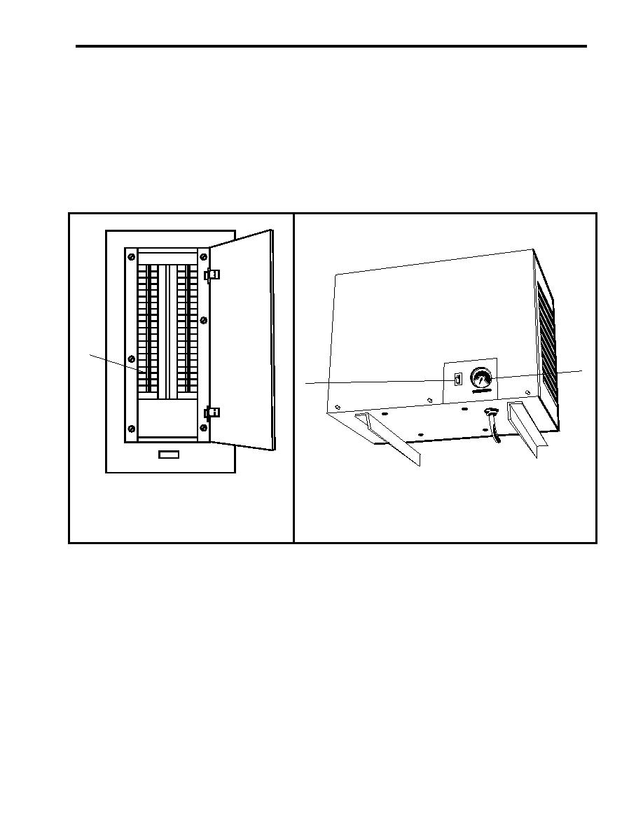
Set J.B. FOR AUTO DRAIN ON AIR RECEIVER. (INC. REFER DRYER), circuit breaker (figure 8,
item 1) on 120V distribution panel No.4 to ON.
(2)
In the forward port corner of the engine room, above SSDG 2:
(a) Set the control air dryer switch (figure 9, item 1) to ON.
(b) Monitor the control air dryer gauge (figure 9, item 2) to ensure normal operation. 125 PSI
(8.6 bar).
1
2
1
Figure 8. 120V Distribution Panel No. 4
Figure 9. Control Air Dryer
SYSTEM SHUTDOWN
1. Check that CA-48 SVCE AIR TK DR valve (figure 1, item 14) is CLOSED.
2. CLOSE valves CA-13 SVCE AIR TK INL (figure 1, item 11), CA-51 AUTO DR (figure 1, item 12), and CA-14
SVCE AIR TK OUT (figure 1, item 13).
3. CLOSE valves CA-40 SVCE AIR TK INL (figure 6, item 1) and CA-39 SVCE AIR TK INL (figure 6, item 2).
4. Set the motor controller MANUAL-AUTO switches (figure 5, item 1) for both compressors to the MANUAL
position.
5. On each motor controller, PUSH the STOP pushbutton (figure 5, item 5) and observe that the MOTOR RUN
indicator light (figure 5, item 4) goes out and that the affected air compressor stops running.
6. Set both motor controller ON-OFF switches (figure 5, item 2) to the OFF position and observe that the
POWER AVAILABLE indicator light (figure 5, item 3) goes out.
0005 00-5

