
TM 55-1930-203-10
compressor drive shaft. The compressed air is stored in two air tanks located below the cargo deck in the forward portion of the
LARC, one port and one starboard. The air tank has a safety valve, manually operated drain valve and an electrically operated
solenoid drain valve. The air tanks are connected so that the air supply system will function properly with only one air compressor
and air tank in working order. Check valves are located in airlines between the air tanks to prevent back blow of air in event of air
compressor failure. Shutoff valves are located in the air tank supply lines for the purpose of shutting off airflow from the tanks if
desired. The tanks are also connected to the air compressors via a shuttle valve and a governor which controls the output of the air
compressors. The governor is set to cut in at 135 p.s.i. and cut out at 155 p.s.i. The shuttle valve prevents back flow of air from one
air tank to the other. b. Maintenance. Operator personnel are not authorized to perform maintenance on the compressed air
system and components. Report all defects to organizational maintenance.
3-14.Steering System
a. Description.
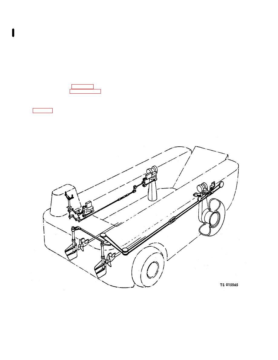
(1) Land steering (fig. 3-19) is accomplished by turning the column and wheel drives. Several modes of operation are
possible and are described in paragraph 2-32. Hydraulic steering cylinders are used to turn the column and wheel drives. Control of
the hydraulic steering cylinders is effected by hydraulic control valves and a mechanical differential linkage. The steering levers in the
cab operate their respective 4ydraulic control valves through jackshafts, steering rods, and bell cranks. The followup rods, attached
to the port wheel columns, center corresponding hydraulic control valves when wheels turn to the desired direction. (2) Marine
steering (fig. 3-19) is accomplished by two rudders located aft of the propellers. The rudders are steered with the forward wheels by
a wire rope connected between the quadrant and starboard wheel column steering arm. Sheaves are provided at various bends and
turns of the wire rope to insure smooth operation.
b. Maintenance. Operator personnel are not authorized to perform maintenance on the steering system. Report all defects to
organizational maintenance.
Figure 3-19. Steering schematic.
Change 4
3-46
