TM 55-4920-384-13&P
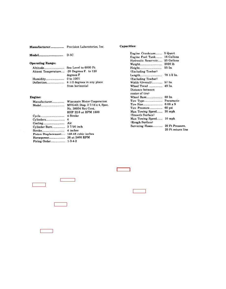
Table 1-1. Test Stand Peculiar Data
C.
Gage Shutoff The gage shutoff valve (13,
scribes, locates and furnishes the operator
panel isolates the Hi-Pressure Gage from the circuit
with sufficient information pertaining to the
for testing.
various controls (Fig. 1-8) and instruments
d. Fluid By-Pass Valve. The fluid by-pass
aircraft hydraulic test stand.
valve (14, Fig. 1-9) is located in the lower left hand
corner of the control panel. It provides a means of
Unloading the pump and diverting the pump output
a. Brake Lever Assembly. The hand brake
into the reservoir or back to the pump inlet. This
lever assembly (7, Fig. 1-8) is mounted on the front
valve must be open, creating a zero pressure condi-
of the frame assembly and sets the brake shoes in
tion, while starting the engine, connecting the test
the rear wheels to secure the test stand in position
stand to the aircraft under test, and while setting
for operation.
the outlet selector valve.
b. Fluid Level Indicator. The fluid level indi-
NOTE
cator (11, Fig. 1-9) is located in the upper right hand
After starting, do not use by-pass
corner of the control panel. It indicates the hydrau-
valve to control pressure. Use compen-
lic liquid level in the reservoir. The dial is marked
sator control.
E, 1/2 and F.

