
TM 55-4920-384-13&P
FAIRBANKS-MORSE TYPE FM-XZE4B7-4 MAGNETO - WlS. MOTOR No. Y-98-C-S1
FOR MODEL MVG4D ENGINE PER MIL-E-11275-C SPECIFICATIONS
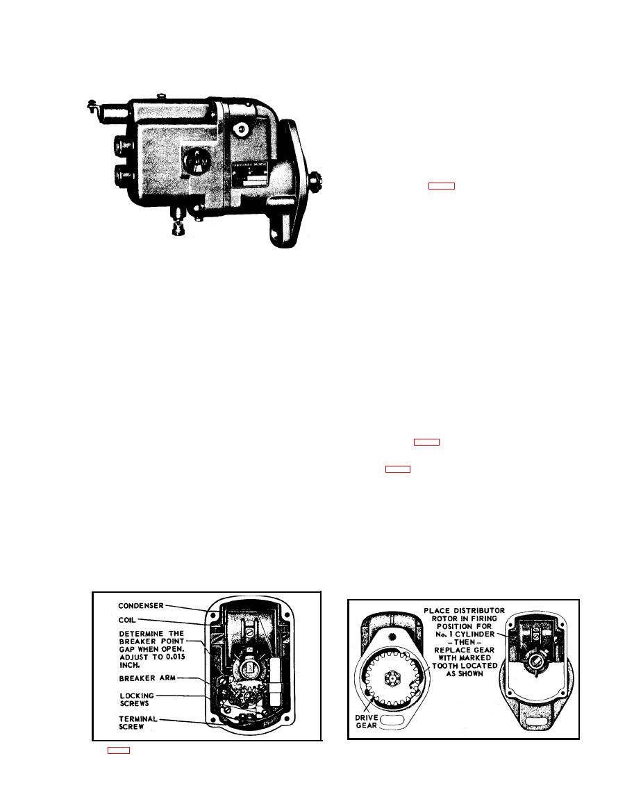
SERVICE OF BREAKER POINTS
The breaker points should be inspected for evidence of pit-
ting or pyramiding. A small tungsten file or fine stone may
be used to resurface the points. Badly worn or pitted points
should be replaced. If it is necessary to resurface or replace
the breaker points, it will also be, necessary to readjust them
to their proper clearance, which is 0.015 in. at full separa-
tion. This adjustment is made in the following manner: Be
sure that the rubbing block is on the high point of the cam,
to secure maximum separation of point a. Loosen the locking
screws identified in Fig. 1. Then, move the contact plate
until the proper breaker point clearance is obtained. This is
accomplished by means of a screw driver inserted in the ad-
justing slot at the bottom of the contact plate and pivoted
between the two small bosses on the bearing support. Locks
the assembly in place by tightening the locking screws and
take a find measurement of the breaker point gap after the
locking screws are tightened.
235655 C-1
FIELD SERVICE NOT RECOMMENDED
FURTHER
The felt wick, if very dirty or completely saturated with
FIELD SERVICE AND ADJUSTMENT lNFORMATION
grease, should be replaced by a clean, dry wick. The cam,
if dry, should he given a light coating of FMCO 10 Magneto
GENERAL DESCRIPTION
Grease. Other than this, the magnetos do not require field
This magneto is a special unit designed and built for use on
lubrication and any attempt to oil or grease the bearing is
engines manufactured by the Wisconsin Motor Corporation
inadvisable. The lubricant should be renewed only during a
The magneto has the standard SAE flange mounting, but has
complete overhaul of the magneto by a Factory-Authorized
a special coupling and drive gear arrangement.
Magneto Service Station.
The magneto has a feed thru condenser, which eliminates
SEALING MAGNETO
the necessity of a shielded ground wire and a witch, when
Before replacing the end cap in the magneto frame, clean the
remote stopping is required. The positive action ground
contact surface a between the cap and the frame. Place a
switch on the magneto is of the push button type, and is
new gasket in the joint, and mount the end cap on the frame,
held in either an open or closed position by a coiled spring.
tightening the four screws securely.
SERVICE PROCEDURE
SPECIAL DRIVE GEAR
Improper functioning of the magneto is often believed to be
The magneto is equipped with a special drive gear mounted
the cause of engine trouble arising from other sources. A
directly on the impulse coupling. If it is necessary at any
brief engine inspection will often locate the trouble before
time to remove the drive gear, special care must be exercised
the magneto is reached and prevent maladjustment of magne-
in reassembly. Remove the engine end cap and turn the rotor
to parts in good condition It is suggested that the magneto
until the contact segment is in firing position for No. 1 cylin-
be opened only when it is certain that the magneto spark
der as shown in Fig. 2. With the distributor rotor in this
produced is unsatisfactory. This condition may be determined
position fit the gear to the impulse coupling lugs so that the
by a simple magneto spark test easily made in the field.
prick punch mark on the rim of the gear is in the position
TESTING THE MAGNETO SPARK
shown in Fig. 2.
Be sure the positive action ground switch is pulled out to
TIMING MAGNETO TO ENGINE
open position before this test is made.
Refer to Magneto Timing instructions, in the front section of
Remove the ignition cable from the No. 1 cylinder end cap
this manual, for proper timing of magneto to the engine.
tower and in its place insert a short piece of stiff wire. Bend
GROUND SWITCH - Positive Action
this wire so it is not less than " from the magneto housing
The new ground switch assembly used on this magneto is of
or the engine block. Turn the engine over slowly and watch
the push button type that stops the engine by grounding the
carefully for the spark which should occur at the instant the
primary circuit. The button is held in contact with the termi-
impulse coupling releases. Repeat this procedure with the
al screw by a spring mechanism, until the engine stops.
remaining towers. If a strong spark is observed from all the
The ground switch button is then pulled out to open the pri-
towers, it is recommended that the magneto be eliminated as
mary circuit, and remains in this position during the operat-
the source of the difficulty and that the cables, terminals,
ing cycle, or until it is pushed in again. The switch must be
and spark plugs be thoroughly inspected. If a weak or no
hand actuated for starting or stopping the engine as it will
ignition spark is noted, check breaker point gap.
remain in either position.-
Fig. 2. DRIVE GEAR MARKING AND ASSEMBLY
D-71
