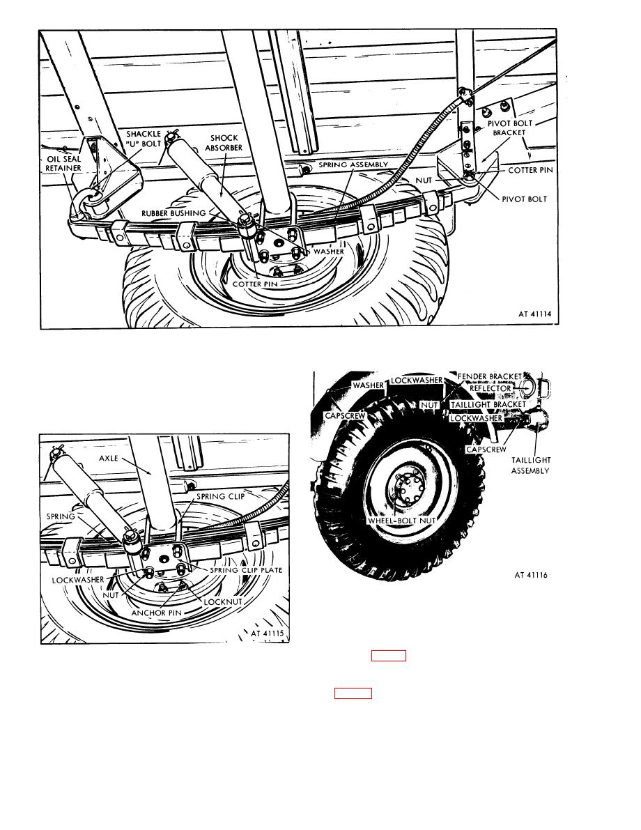
Figure 1-4. Spring and shock absorber installed.
c. Axle (fig. 1-5). The axle is of a one-piece
tubular design. It is fastened to the springs by
means of U-shaped clips and the spring clip plates.
The axle is flanged to mount the brake backing
plate.
Figure 1-6. Wheel, fender, and taillight installed.
e. Parking Brake. The brake system is a hand-
operated internal expanding, double anchor, two-
shoe type parking brake with cable control. The
hand lever (fig. 1-1) is located on the front of the
Figure 1-.5. Axle installed.
body on the right side. It controls the two brake
d. Wheels and Tires (fig. l-6). The wheels are of
cables through a lever rod, bellcrank, and adjusting
t w o - p i e c e riveted steel construction and are
rod (fig. 1-7). The hand lever assembly includes a
fastened to the wheel hub by five wheel bolts and
ratchet mechanism which holds the brakes in the
nuts. The vehicle is equipped with nondirectional
applied position until released.
7:00-16, 6-ply mud and snow tires.
1-4

