
TM 9-2330-211-14&P
3-9.
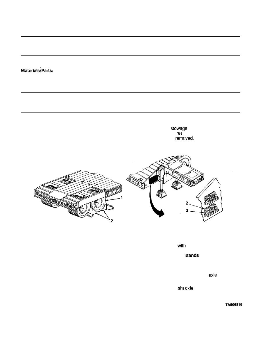
WHEEL AND TIRE ASSEMBLY
This Task Covers:
Installation
b.
a.
Removal
Initial Setup:
Tools/Test Equipment
Jack and handle, hydraulic
4 x 4 x 6 wooden blocks
q
q
q Wrench and handle, IL g
Personnel Required: Two
ACTION
REMARKS
ITEM
LOCATION
REMOVAL
a. Take out of
bracket (3).
Chock blocks (2)
Wheel and tire
1.
r of wheel and tire assemblies
b. Block front and
assemblies (1)
(1) not being
NOTE
The inner and outer nuts are marked
either an R or L. The
R stands for right-hand threads; right-hand nuts are turned
counterclockwise for removal. The L
for left-hand
threads; left-hand nuts are turned clockwise for removal.
Two types of nuts are shown, depending on the semitrailer.
Place between stop block (4) and
(8).
Wooden blocks (7)
2.
Stop block (4)
and axle (8)
a. Position under
box bracket (6).
Hydraulic jack (5)
3.
Shackle box
b. Using handle, raise until it touches shackle box
bracket (6)
bracket (6).
3-18
