
TM 9-2330-294-14
(2) A fail-safe release system is provided to
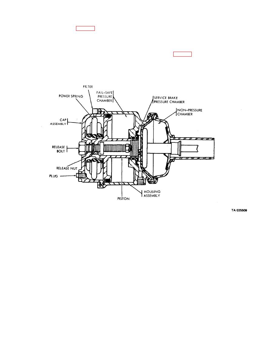
(1) The fail-safe units are spring-powered brake.
allow the vehicle to be moved short distances when
its air system is disabled. A control knob, located on
actuators that assemble piggyback on one air
chamber of each brake. When 65 psi or more air
the left side of the semitrailer, releases sufficient air
from an air tank to release the fail-safe brakes for a
pressure is applied against the piston in the fail-safe
head pressure chamber, the spring will push the
short time (para 2-4b).
piston against the diaphragm plate and apply the
brakes. One fail-safe unit is located at each trailer
wheel .
