TM 9-2330-373-14 & P
4-34. AIR SUSPENSION SYSTEM (cont)
REMOVAL OF RUBBER BUSHING AND TORSION BAR (cont)
5.
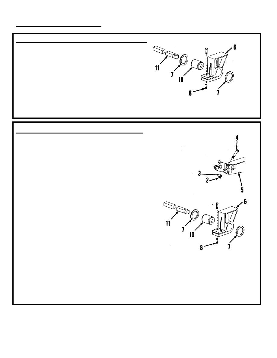
Loosen nuts (8) securing frame bracket (6).
6.
Drive torsion bar (11) completely out of
assembly, using care not to mushroom torsion
bar end.
7.
Carefully let both equalizing arms down away
from frame brackets.
6.
Bracket
10.
Rubber bushing
8.
Push out rubber bushing (10) and spacers (7).
7.
Spacer
11.
Torsion bar
8.
Nut
INSTALLATION OF RUBBER BUSHING AND TORSION BAR
1.
Insert rubber bushing (10) and rotate, as near as
possible, to operating position.
2.
Place spacers (7) on ends of bushing (10) and
move equalizing arms (5) back to their positions
relative to frame brackets (6).
3.
Line up square holes in bushing with square
holes in equalizing arms to receive offset cap
screw (4).
4.
Insert torsion bar (11) through ends of equalizing
arms and bushings. Make sure notch in torsion
bar is alined to receive offset cap screw (4).
5.
Jack up axle to proper design height from
horizontal axle centerline to underside of frame
(14 inches, plus or minus one-eighth of an inch).
Tighten nuts (8) with axle in proper height
position to a torque of 150 lb-ft (203.4 Nm).
6.
Install cap screws (4), lock washers (3) and nuts
(2) and tighten to a torque of 200 lb-ft (271.2
2.
Nut
Nm).
3.
Lock washer
4.
Cap Screw
5.
Equalizing arm
6.
Bracket
7.
Spacer
8.
Nut
10.
Rubber bushing
11.
Torsion bar
7.
Reconnect linkage to height control valve.
8.
Install wheels and remove blocking and jacking equipment.
TA 314812
4-93

