TM 9-2330-384-14&P
4-35. BRAKE SHOE REPLACEMENT (Con't).
b. INSPECTION
(1) Inspect all removed components
for damage. If damaged, re-
place.
(2)
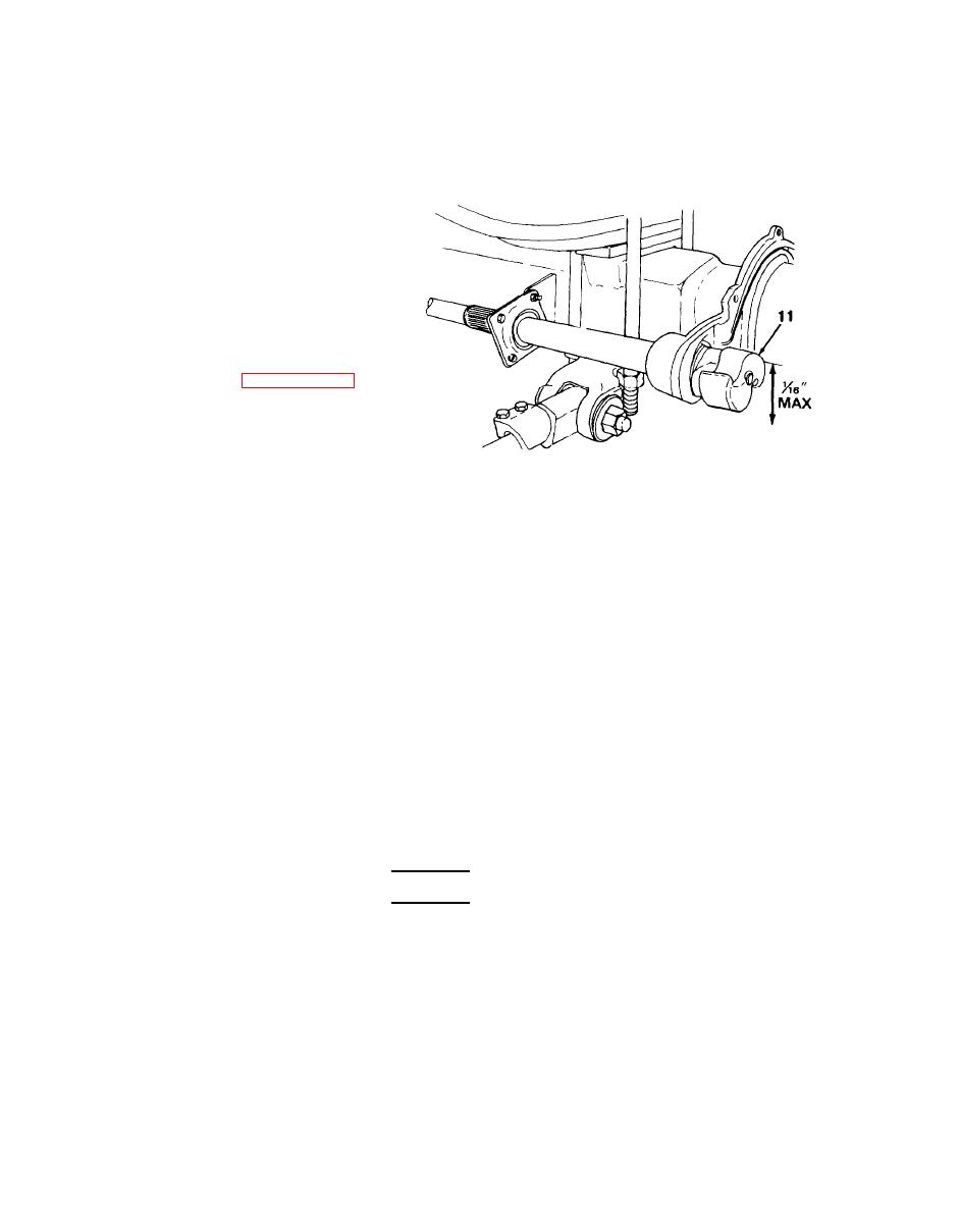
Move S-cam (11) of camshaft up
and down by hand, and use a
steel rule to measure up-and-
down movement. If movement is
greater than 1/16 in. (1.59 mm),
perform camshaft maintenance
to replace camshaft bearings and
bushing (see paragraph 4-36).
(3)
Inspect spider (7) for damage. If spider is damaged, notify direct support maintenance to
replace axle.
Inspect two anchor pins (6) for wear and looseness in bushings (5). Anchor pin should slide
(4)
smoothly inside bushing.
(5)
Install anchor pin (6) inside bushing (5) and move anchor pin up and down by hand. Use a
steel rule to measure the up-and-down movement. If movement is greater than 1/16 in.
(1.59 mm), anchor pin and bushing must be replaced.
Cut a slot in bushing (5) with a hacksaw blade. Use a chisel to drive out bushing, Discard
(a)
bushing.
(b) Grease new bushing (5).
Use a block of wood to drive bushing squarely into spider (7).
(c)
c. INSTALLATION
WARNING
Wipe clean excessive lubricant in the area of brake shoe linings to avoid
grease soaking the linings. Replace grease soaked brake shoe linings. Fail-
ure to follow this warning may cause brakes to malfunction, resulting in
serious injury or death to personnel.
(1)
Apply an even coat of grease to two anchor pins (6) and bushings (5). Wipe off excess
grease.
(2)
Position top brake shoe (2) over spider (7).
(3)
Install two new shoe retainer springs (1) to top brake shoe (2) at anchor pin (6) end.
4-102


