
TM 9-2330-388-14
(b) In the composite light box, locate the lead
(h) Thread a lacing wire through conduit from
that comes from the triple marker box, fig.412.
the light box to the other. Attach lead assembly to lacing
Disconnect this wire from the connector lead assembly.
wire and pull the lead into the right marker box.
Cut th terminal from the lead.
(i)
Install new terminal onto the lead assembly.
(c) Remove the three marker lights from the
(j) Connect right center marker light lead to the
triple marker box, but do not remove the washer and
shell from the light leads, para 4-12.
lead assembly. Replace gasket and cover. Secure with
four screws.
(d) Pull old wire lead through conduit and out
(k) In the left marker box, connect the two
through one of the openings in the triple marker box.
harness leads (No. 21489) to the new lead assembly.
(e) Starting at left composite light box, thread a
Connect the left marker light lead (No. 489) to the lead
lacing wire through conduit into triple light box. Attach
assembly. Replace gasket and cover. Secure with four
lacing wire to lead and pull lead through conduit into
screws.
composite light box.
(I)
Test operation of lights.
(f) Install new terminal onto lead. Connect the
(4) Front
Marker
Light
Lead
Assemblies
marker light lead assembly to connector lead assembly,
Replacement.
(g) Replace composite light box covers and
(a) Remove both front marker light box covers
gasket. Secure with six screws.
and gaskets by removing eight screws from each box
cover and disconnecting the marker light electrical lead
(h) Connect the marker light leads to the triple
(No. 489), fig. 4-13.
marker light lead assembly.
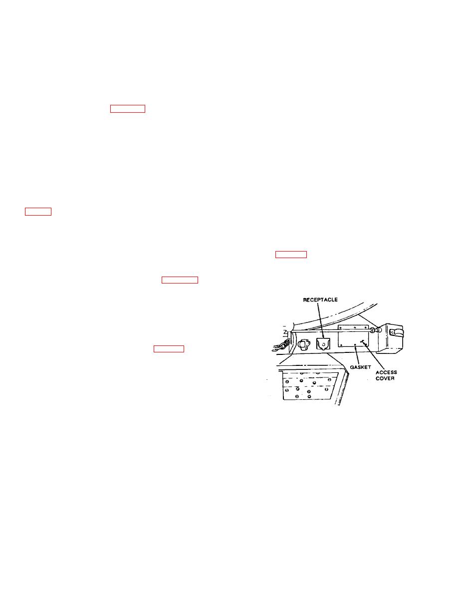
(b) Remove six screws from the front electrical
(i)
Replace triple marker lights, para 4-12.
access cover, remove cover and gasket.
(j) Test operation of Lights.
(3) Right Side Marker Light Lead Assembly
Replacement.
(a) Remove four screws that secure right
marker light box cover to the light box, fig. 4-14.
(b) Disconnect the marker light lead from the
right center marker light lead assembly, then remove the
cover and gasket.
(c) Cut the terminal from the marker light lead
assembly.
Figure 4-9. Front Access Cover
(d) Remove the four screws that secure left
(c) From inside electrical access hole,
side marker light box cover to the light box. Remove
disconnect the left marker light lead assembly from the
cover and gasket.
right marker light lead assembly. Disconnect right
marker light lead assembly from receptacle wire lead
(e) Disconnect the marker light lead and
(No. 21-489) and wire harness lead (No. 21 - 489).
remove gasket and cover.
(d) Cut the terminal from the right marker light
(f) Disconnect the marker light lead assembly
lead assembly in the right marker box.
from the two wire harness leads.
(e) From inside the left marker light box, pull
(g) Pull the old marker light lead assembly
the old right marker light lead assembly from the conduit.
through the conduit and out the left marker light box.
4-75
