

Custom Search
|
|

|
||
 TM 9-2330-394-13&P
ELECTRICAL SYSTEM TROUBLESHOOTING - Continued
0036 00
ELECTRICAL SYSTEM - Continued
Table 1. Electrical System Troubleshooting Procedures - Continued
MALFUNCTION
TEST OR INSPECTION
CORRECTIVE ACTION
13. LEFT BLACKOUT STOPLIGHT
3.
Connect positive (+) probe
DOES NOT ILLUMINATE -
of digital multimeter to one
CONTINUED
terminal of circuit breaker
CB2.
4.
Connect negative (-) probe
of digital multimeter to other
terminal of circuit breaker
CB2.
5.
If continuity is not present,
replace circuit breaker CB2
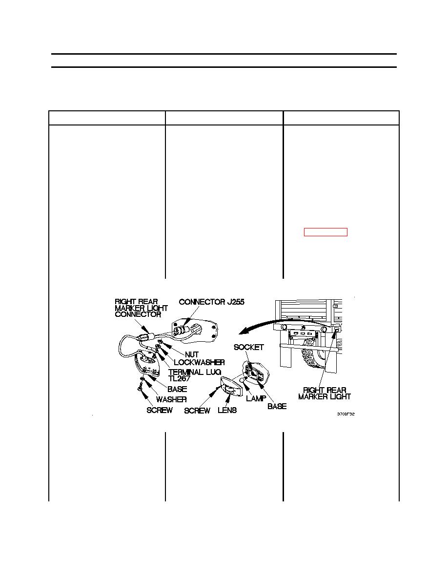
14. ALL REAR LIGHTS DO NOT
Check to see if continuity is
1.
Remove two screws and lens
ILLUMINATE
present between terminal lug
from base of right rear
TL267 and a known good
marker light.
ground.
2.
Remove lamp from socket.
3.
Remove four screws and
washers from base.
4.
Extend base and disconnect
connector J255 from right
rear marker light connector.
0036 00-89
|
||
|
||


