

Custom Search
|
|

|
||
 TM 9-2330-394-13&P
BRAKE SYSTEM TROUBLESHOOTING - Continued
0037 00
BRAKE SYSTEM - Continued
Table 1. Brake System Troubleshooting Procedures - Continued.
MALFUNCTION
TEST OR INSPECTION
CORRECTIVE ACTION
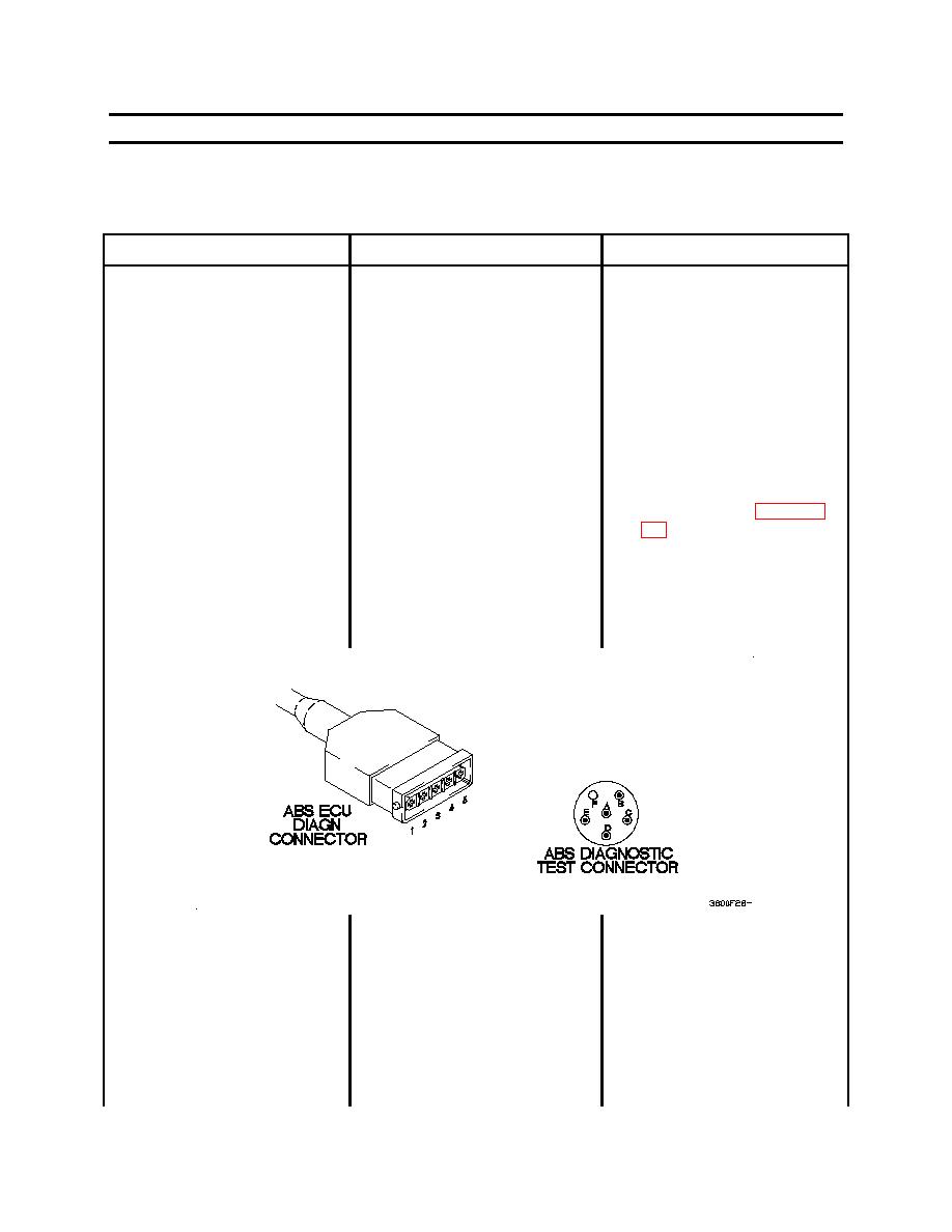
6. ANTI-LOCK BRAKING
5.
Connect positive (+) probe
SYSTEM (ABS) DIAGNOSTIC
of digital multimeter to ABS
TOOL DOES NOT OPERATE -
diagnostic test connector pin
CONTINUED
A.
6.
Connect negative (-) probe
of digital multimeter to ABS
ECU DIAGN connector pin 1
and note reading on digital
multimeter.
7.
If continuity is not present,
replace ABS control to
diagnostic cable (WP 0072
1.
Set digital multimeter to
2.
Check to see if continuity is
ohms.
present between ABS
diagnostic test connector pin
B and ABS ECU DIAGN
connector pin 2.
2.
Connect positive (+) probe
of digital multimeter to ABS
diagnostic test connector pin
B.
3.
Connect negative (-) probe
of digital multimeter to ABS
ECU DIAGN connector pin 2
and note reading on digital
multimeter.
0037 00-28
|
||
|
||


