
C3, TM 9-2350-230-12
23
FUEL PUMP: Shut off fuel supply (valve is located just below adapter, item 43). Disconnect fuel pump
outlet tube (26) from adapter (24) at fuel pump. Disconnect fuel pump inlet hose (44) from elbow (9).
Disconnect power lead from harness (7) and remove screw (19) and washer 20). Remove two nuts (16)
holding pump to bracket, and remove fuel pump assembly.
36
COOLANT PUMP: Disconnect power lead from harness (7) and disconnect ground lead at fuel pump
bracket. Loosen clamps (11), and disconnect inlet (41) and outlet (45) hoses. Remove two clamps (34
and 35) and remove coolant pump.
42
BATTERY HEATER: Disconnect and remove batteries (figure 9-97). Loosen two clamps (11) and
disconnect inlet (44-1) and outlet (41) hoses. Remove heater tray.
56
SHOCK MOUNTS: Remove coolant heater (item no. 8 above). Remove two screws (2) and washers (47,
47-1) to remove each heater bracket (55 and 58). On right bracket, also remove screw (66), washer (20)
and harness clamp. Remove nuts (51) washers (29, 52) screws (59, 64), exhaust pipe bracket (53, left
bracket only), snubbing washers (54) and 'cradles (60, 63). Drill or punch out rivets (57) to remove shock
mounts.
62
FUEL FILTER: Shut off fuel supply (valve is located just below adapter, item 43). Refer to figure 9-134 for
filter service. OTHER COMPONENTS: Replace unserviceable components as required.
INSTALLATION
Reverse removal procedure.
Whenever coolant lines have been disconnected it is necessary to bleed air from the system as follows:
Disconnect coolant heater outlet hose (12) at elbow (10). Add coolant at surge tank until coolant spills
from both elbow and hose. Reinstall hose on elbow without allowing air to enter either hose or elbow.
Tighten clamp and continue adding coolant until full level is reached in surge tank.
After engine has been run to raise coolant pressure in system make visual check of all hose connections
for leaks.
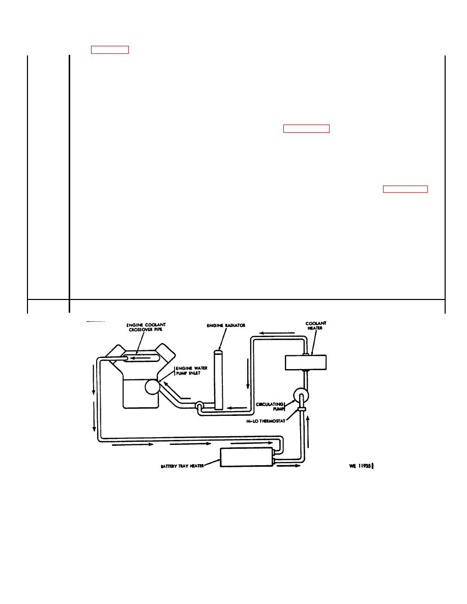
Figure 12-6. (Added) Winterization kit coolant flow diagram.
12-8
