
TM 9-2590-209-14&P
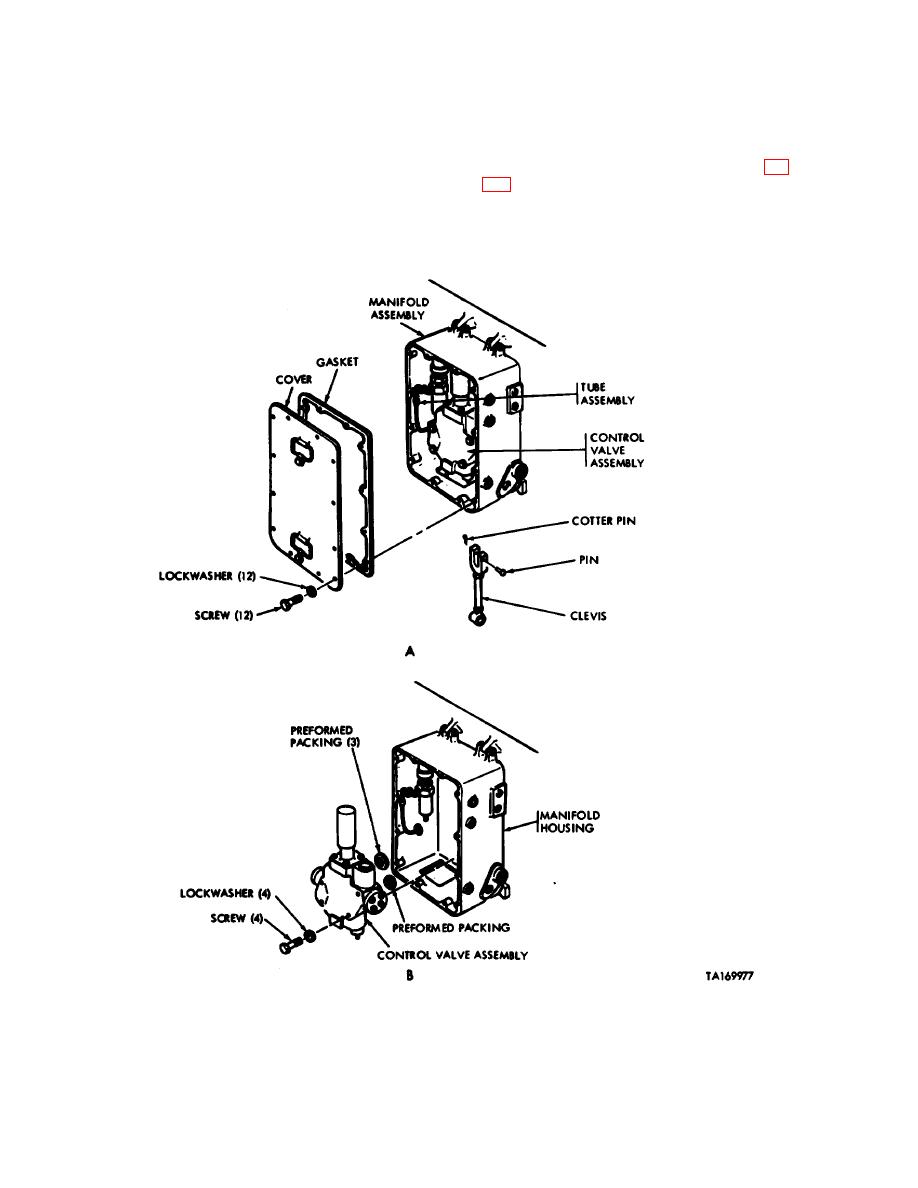
c. Connect tube assembly to control
e. Install cover and gasket to manifold
valve assembly (view A).
assembly, and secure with 12 screws and
lockwashers (view A).
d. Pull clevis rod through bottom of
f. Fill and bleed hydraulic system (fig
manifold assembly housing, and secure to
control valve assembly with pin and cotter
pin (view A).
Figure 4-15. Removal or installation of manifold control valve assembly.
4-34
