
TM 9-2590-209-14&P
Table 10-1. Special Tool (Early Model Bulldozer)
Identification
References
Item
Number
Fig Para
Use
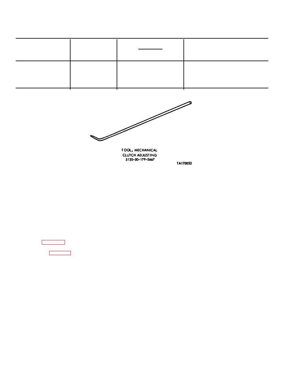
1. Tool: mechanical
5120-00-179-5667
10-1 10-30
Adjust right-angle
clutch adjusting
drive mechanical
(carried on engine
clutch.
shroud access door).
Figure 10-1. Special tool (early model bulldozer).
Section III.
OPERATING INRUCTIONS
housing. The detents in the mechanical clutch control
10-7.
Introduction.
handle housing secure the clutch in the engage or
disengage position.
Push the handle to engage
a. This section contains operating instructions
mechanical clutch and pull to disengage.
and information needed to locate and operate early
model bulldozer controls and instruments.
b.
Carrying Hooks Control Handle.
b. Prior to operating bulldozer, perform before
The carrying hooks are engaged or disengaged by a
operation preventive maintenance checks and services
manually operated control handle mounted on the hull in
contained in table 10-2.
front of the driver's hatch. Pushing the control handle
releases the carrying hooks when the blade assembly is
10-4.
Control (Fig 10-2).
raised.
a. Mechanical Clutch Control Handle. The
c. Blade Assembly Manual Control Lever.
mechanical clutch is controlled by a handle located in the
The directional control valve lever that controls the blade
crew compartment on the left side of the bulkhead. A
assembly operation is located in the driver's
flexible control cable extends from the bulkhead through
compartment. Move-
the engine compartment to a yoke attached to the clutch
10-2
