
TM 9-2590-209-14&P
(2) Lengthen or shorten cable by screwing
clevis in or out until holes in clevis align with hole in yoke
NOTE
arm.
Procedures for both left and right sides are the same.
(3) Install clevis pin and secure with cotter pin.
(1) Remove four screws securing top guard
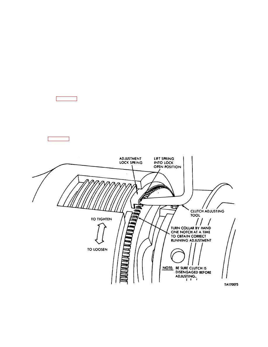
(4) Check operation of control cable and yoke
to rear guard (view A).
to make certain that when in disengage detent position
there is a 0.010 inch clearance of the dogs and that
(2) Remove four screws, washers,
and
when in the disengaged detent position (handle in) that
lockwashers securing top guard to front guard. Remove
the mechanical clutch is fully engaged.
top guard (view B).
10-31. Maintenance of Cylinder Assembly Guards.
(3) Remove two screws, washers,
and
lockwashers and remove front guard (view B).
a. Description (Fig 10-21). Each cylinder assembly
(4) Remove four screws, washers,
and
is protected by a top guard, bottom guard, front guard,
lockwashers and remove rear guard (view C).
and a rear guard. The guards are secured to the
cylinder mounting brackets by screws, washers, and
(5) Remove four screws and lockwashers and
lockwashers. The installed guards are designed to
remove lower guard and two spacers (view D).
protect the cylinders from damage by brush, rocks, and
debris.
b. Removal (Fig 10-21).
Figure 10-20. Mechanical clutch adjustment (early model bulldozer).
10-36
