
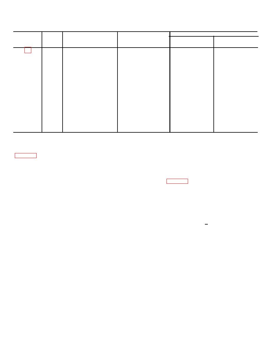
Table 4-8. Repair and Rebuild Standards for
Moldboard Cylinder and Ram
Figure
Refer-
Point of Measurement
Size and Fit of New
Wear Limits
Number
ance
Parts
Direct &
Depot
Letter
General Support
Support
(∗)
(∗)
6.975 to 6.985
OD of piston
A
7.015 to 7.020
ID of cylinder bore
B
4-3
(∗)
(∗)
0.030L
Fit of piston in cylinder
A-B
4-3
(∗)
(∗)
to
4.045L
2.503 to 2.506
ID of packing gland
C
4-3
(∗)
(∗)
2.498 to 2.501
OD of piston rod
D
4-3
(∗)
(∗)
0.002L
Fit of piston rod in gland
C-D
4-3
(∗)
(∗)
to
0.008L
2.375 to 2.376
ID of ram head bore
E
4-3
(∗)
(∗)
2.377 to 3.379
OD of bushing
F
4-3
(∗)
(∗)
0.001T
Fit of bushing in ram
E-F
4-3
(∗)
(∗)
to
0.004T
2.003 to 2.005
ID of bushing
G
4-3
2.010
2.008
cotter pin (5).
e. Assembly. During assembly, replace packing
(12) Install ring (12) in groove in cylinder (4).
set, seals, and/or all worn or deformed parts. To
(13) Slide piston assembly into cylinder (4).
assemble the moldboard cylinder and ram, refer to
(14) Install eight washers and screws (15 and
14) to secure cylinder head (13) to cylinder (4).
(1) Install bushing (23) in run head (22).
f. Test. To test the hydraulic cylinder and ram,
(2) Connect threaded ram head (22) to piston
proceed as follows.
rod (21).
(1) Connect a test arrangement to the cylinder
(3) Install packing set 116) into internal bore of
as shown in figure 4-4.
cylinder head (13).
(2) Cycle the hydraulic cylinder through its full
(4) Using two screws (191, secure packing
stroke at least five (5) times by applying pressure
gland (17) to cylinder head (13). Secure screws (19)
alternately to port A and B. There shall be no exterior
with lockwire (20).
leakage. Linkage past the rod seals during cycling test
(5) Install seal (18) in packing gland (17).
shall not form one (1) drop.
(6) Slide piston rod (21) into cylinder head (13)
(3) Apply pressure at port B and retract the
bore.
cylinder to its minimum length and then disconnect the
(7) Slide washer (11) over piston rod 121).
line at port A. Apply 1000 + 50 psi at port B and
(8) Install piston (101 on piston rod (21).
(9) Install packing set (91 on piston (10).
observe for leakage at port A. This leakage shall not
(10) Install piston ring (17) on piston (8).
exceed three (3) cubic inches per minute during the fifth
Install piston (8) on piston rod (21) to mate with packing
minute of a five-minute pressure test period. There
set 19).
shall be no rod seal leakage or exterior leakage.
(11) Install nut (6) on piston rod (21) and install
4-12
