
A. LUBRICATION.
SAW BLADE GUIDE ROLLERS
Clean and lubricate with a light to medium weight oil,
daily for heavy use and weekly for occasional use.
VISE SLIDE WAYS
VISE SCREW
We do not recommend any lubrication. If it is greased
RING GEAR
or oiled it will pick up dirt and shavings which would
normally fall away.
GUIDE BEAM
This should be kept clean, with a light film of oil
maintained on it.
A few drops of light to medium oil should be applied
CUTTING HEAD PIVOT POINTS
weekly.
CYLINDER PIVOT POINTS
BLADE TENSION SCREW
VARIABLE SPEED DRIVE PULLEY
Grease monthly (Fig. 13).
The oil level of the hydraulic cylinder should be
stalled on the machine. If a blade that is worn or
maintained within l/2" from the top, with the
stretched out of shape is used to make this ad-
piston rod all the way down. This will require
justment, the end result may not be satisfactory.
occasional filling with a medium grade of hydraulic
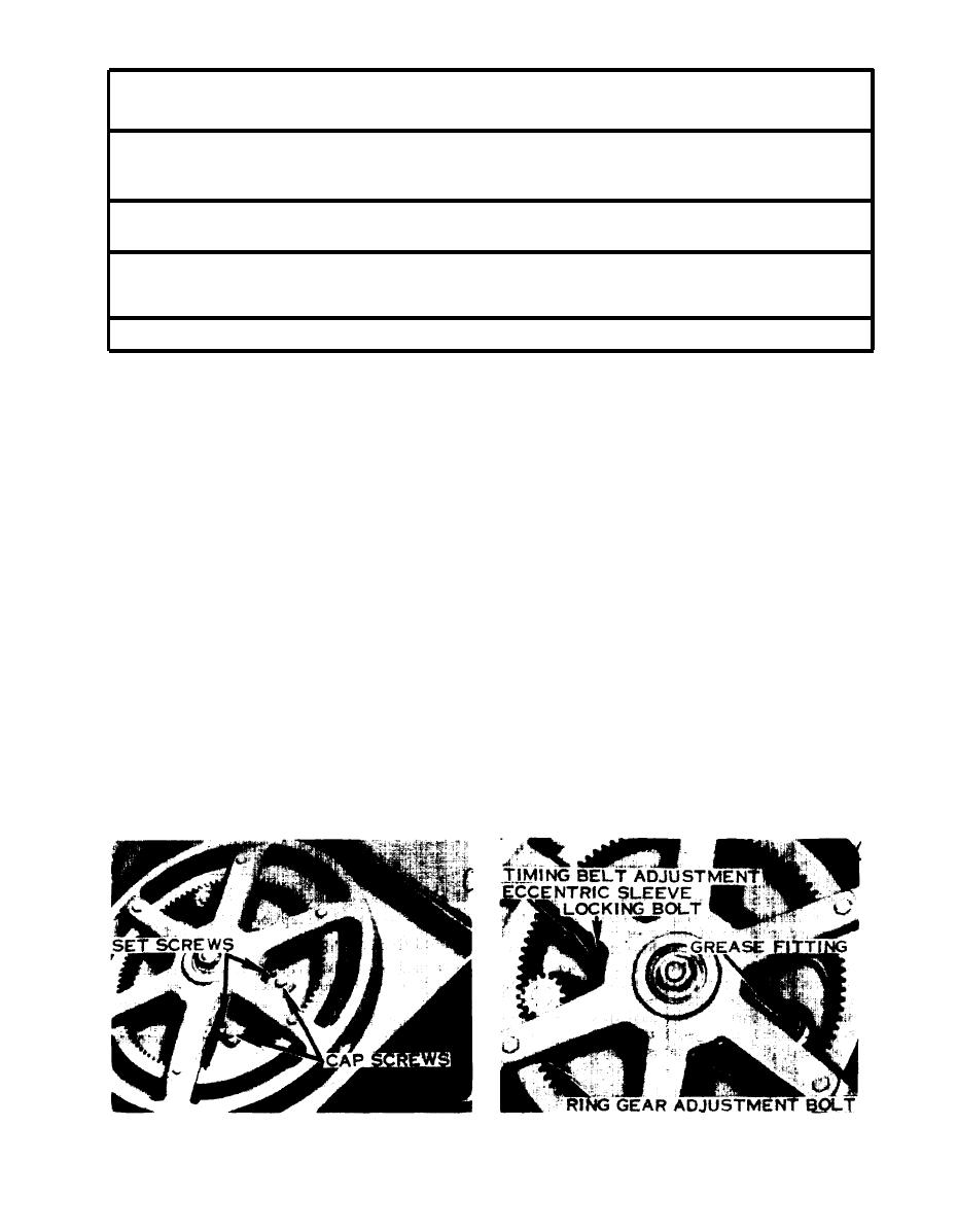
To make a wheel pitch adjustment, release the
oil. If the oil level falls below the top hose fittings in
blade tension and loosen the cap screw in the outer
the cylinder, the cutting head action will become
edge of the wheel axle plate (Fig. 12). Turn the
spongy and a considerable drop in the head will be
socket set screws next to them in or out to get the
noticed after the head is raised and released onto
desired change of axle inclination. If the blade is
the hydraulic cylinder. If this happens, remove the
running hard against the wheel flange, turn the set
cylinder cap and fill the cylinder. Replace the cap,
screws out (counterclockwise) and retighten the cap
leaving it loose, and work the head up and down 8
screws. This will lower the outer edge of the wheel,
or 9 times, closing the cutting head descent valve
reducing the tendency of the blade to run against
each time before the head is lifted. Remove the cap
the flange. If the blade runs down away from the
and refill the cylinder. Repeat this cycle until all air
flange, turn the set screws in (clockwise) and
tighten the cap screws. This will raise the outer
has been worked out of the system and the oil level
edge of the wheel, causing the blade to run closer to
does not fall between cycling periods.
the flange.
B. BLADE WHEEL ALIGNMENT. When the
blade wheels are properly adjusted, the blade will
C. RING GEAR AND PINION ADJUSTMENT.
run with the smooth edge making light contact
The ring gear and pinion should be adjusted to
with the wheel flanges. If this contact becomes too
.010" to .015" clearance between the two gears.
heavy, it will wear the wheel flange unduly and
To make this adjustment, loosen the cap screw in
create a noisy scrubbing sound. It also causes an
the lower edge of the pinion bearing flange (Fig.
edgewise strain on the blade at the point of wheel
13). Lightly tap the flange in the direction desired
contact which can cause blade fatigue and
to get the proper clearance, then tighten the cap
breakage.
screw and check the clearance. Be sure to have a
blade on the machine, under normal tension, when
Before making any blade wheel pitch adjustments,
making this adjustment.
we strongly recommend that a new blade be in-
Figure 13
Figure 12
24
