TM 9-3418-200-14 & P
The table travels horizontally on a cross rail (R, fig. 1) and vertically on dovetailed ways on the front of the column (3, fig.
2). The vertical travel of the table is regulated with the ball crank (P, fig. 1) and is locked in any given position with the lock
handle (8, fig. 4). The horizontal travel of the table may be operated by hand with the ball crank (Q, fig. 1) or automatically
by means of the feed rod (O, fig. 1). The automatic feed may be engaged or disengaged by means of the pawl (14, fig. 3).
The arrow on top of the pawl indicates the direction the table will travel automatically when the pawl is engaged.
The table support (T, fig. 1) is always lowered against the machined surface on the base and locked in position with the
locking handle (fig. 32). The flexible stem of the work lamp is fastened to the table support and the lamp cord is plugged
into the receptacle on the bottom of the switch box (fig. 1). The switch box contains an on and off push button switch for
operating the shaper and a toggle switch for operating the work lamp.
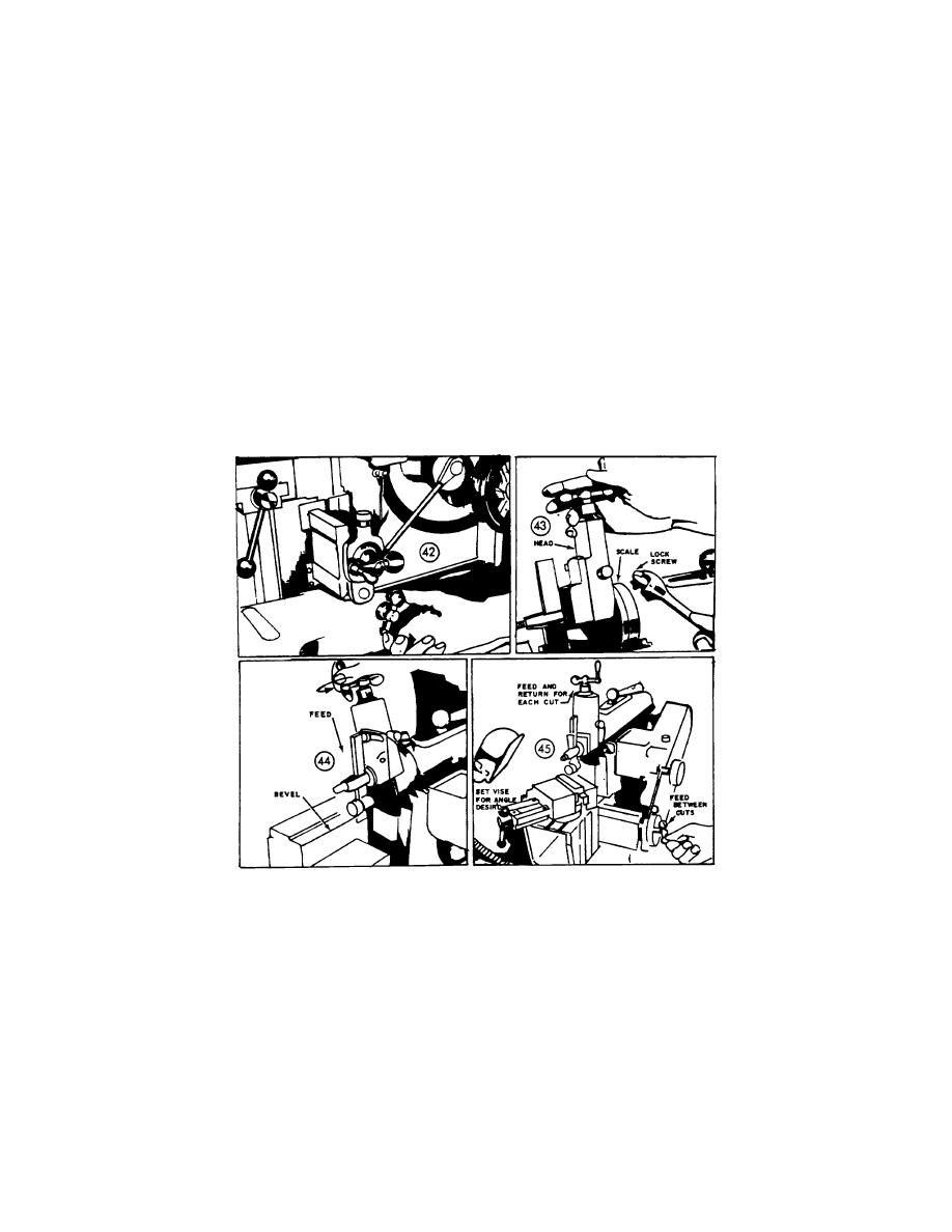
The clapper box should be tilted by releasing the lock screw as shown in figure 33 and moved in such a way that on the
return stroke of the ram the clapper block lifts up and away from the work being cut.
The hand-wheel (H, fig. 1) is used for checking and adjusting stroke position, and should always be used to operate the
ram for one complete stroke before turning on the power, thus, avoiding any mis-adjustment which may result in ram ways
striking the vise, work, etc.
17

