TM 9-3431-254-14&P
L-57, L-77
Series
CARBURETOR
MODEL 87A8
OPERATION and SERVICE
main jet. Fuel from the float chamber flows through the
DESCRIPTION
main jet into the metering well. Fuel for idling is drawn
The
87-Series is a horizontal carburetor with a con-
from this well through the calibration, or metering orifice,
centric fuel bowl. It is a "balanced" carburetor, because
in the center of the idling jet. AS the fuel reaches the
all air for fuel chamber and metering well ventilation and
idling channel it is mixed with air which is admitted
idling must come through the air cleaner. Air cleaner
through a calibrated orifice in the channel from the inside
restrictions have a minimum influence on the fuel-air ratio
of the air intake to form an emulsion. This emulsion is
when a carburetor is thus "balanced".
discharged into the air stream, to form the idling mixture,
through two holes one of which is controlled by the idle
The main jet and discharge jet are centrally located. The
adjusting needle. Turning the adjusting needle counter-
metering well which completely surrounds the discharge
clockwise (out) permits more of the emulsion to reach the
jet is in the center of the fuel bowl assembly. This con-
air stream and make the idling mixture richer while turning
struction permits extremely high angle operation in any
the needle in (clockwise) cuts off the amount of the emul-
direction.
sion reaching the air stream and makes the mixture leaner.
The venturi, which is part of the throttle body casting,
measures the volume of air that passes through the car-
buretor. In selecting the venturi size, the smallest size
As the throttle is opened, the suction on the idling system
that will permit full power development should be used.
diminishes, but the increased volume of air entering the
engine through the venturi creates sufficient vacuum
(suction) on the discharge jet to draw an emulsion of fuel
and air from the metering well which receives its fuel from
the main jet and its air from the well vent. The flow
characteristics of the discharge jet are influenced by the
size, location, and number of holes in the sides of that
part of the jet which is in the metering well, as well as by
OPERATION
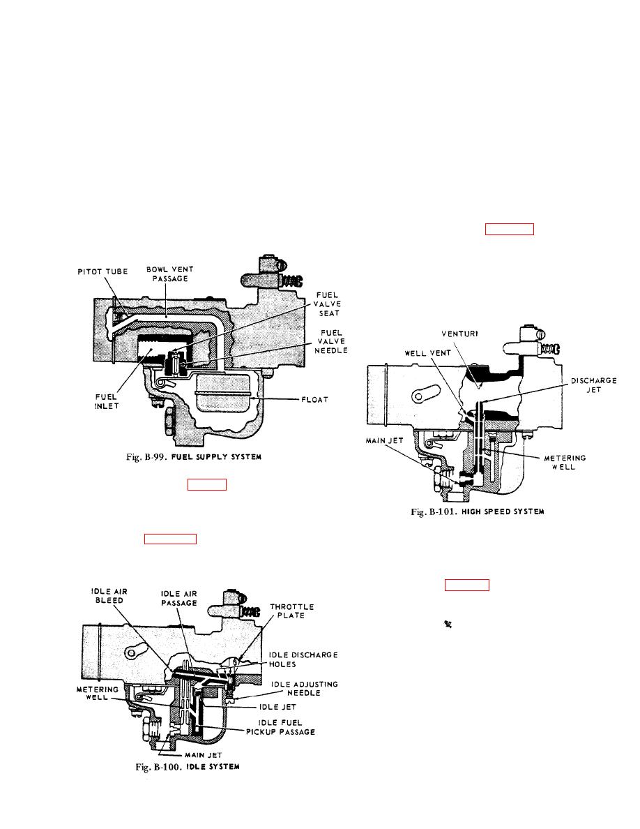
FUEL SUPPLY SYSTEM (Fig. B-99)
Fuel under normal pressure entering the float chamber
through the fuel valve seat is controlled by the twin float
which, moving on its axle, closes the needle valve when
the fuel reaches the proper level in the bowl.
the sizes of the discharge jet orifice, the size of the main
jet, and the size of the well vent. The well vent is located
in the air intake and permits air to enter the top of the
At idling speeds the throttle plate is almost closed, thus a
metering well around the outside of the discharge jet. The
very high suction exists at the edge of the throttle plate
flow of fuel through the main jet is controlled by the size
where the idle discharge holes are located. All fuel for
of main jet opening.
idling and part throttle operation is supplied through the
Starting a coId engine requires a much richer mixture of
fuel and air. Moving the choke lever to close the choke
plate restricts the air entering the carburetor (except at the
pitot tube, Fig. to the bawl vent) and increases the
suction on the idling system which makes the mixture
richer.
STARTING THE ENGINE
Before cranking the engine, the carburetor throttle should
be opened a little to expose both idle discharge holes to
suction The choke should be fully closed until the engine
starts, then opened a little to prevent stalling from being
over-choked, then when the engine is fully warmed up the
choke can be returned to wide open position and the
throttle closed to the idling position.
ADJUSTMENTS
Adjust the throttle stop screw to obtain the desired idling
speed by turning screw in (clockwise) to increase speed
and out (counter-clockwise) to decrease engine speed.
B-73


