TM 9-4120-395-14&P
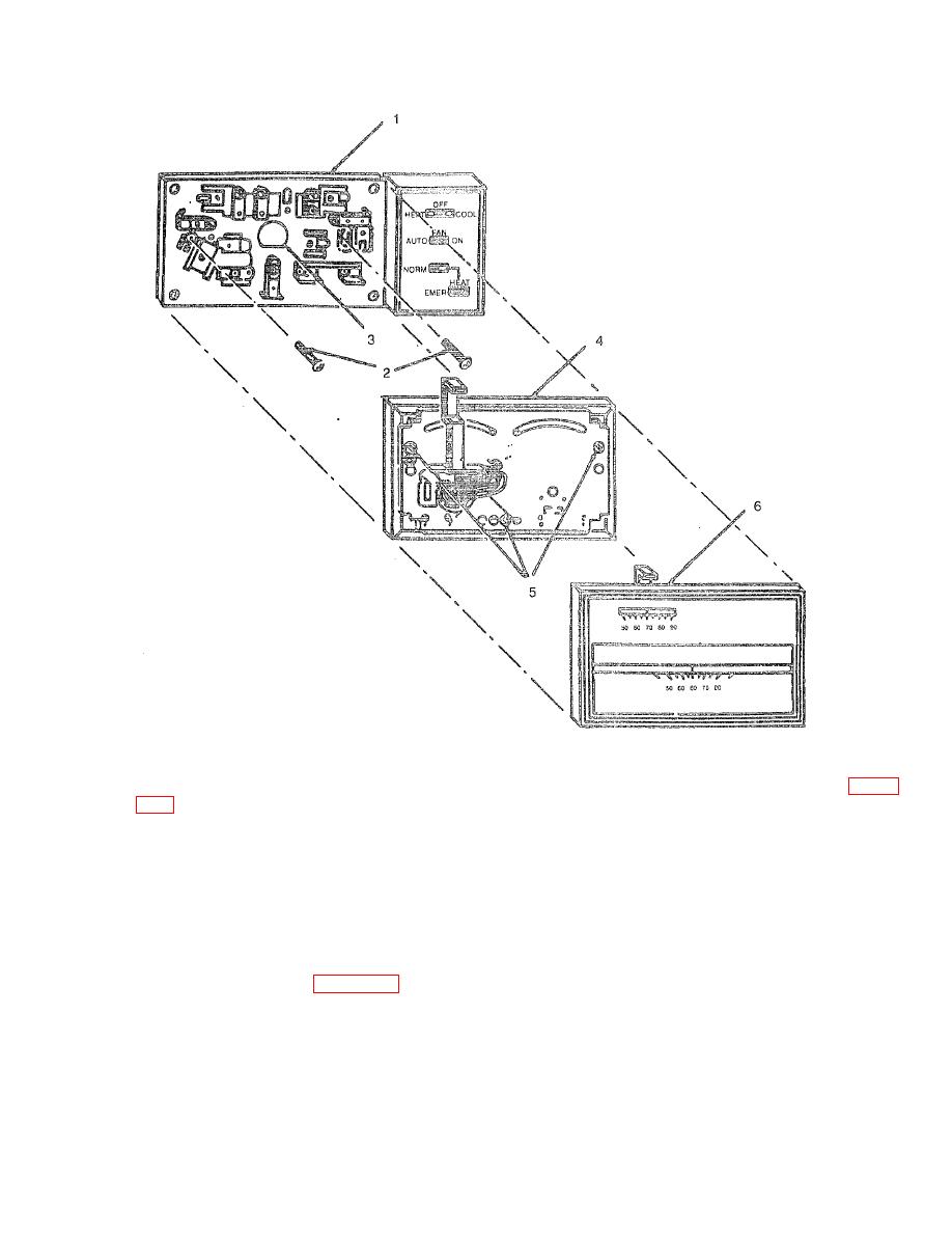
Figure 4-10. Thermostat Assembly.
(5) Level the subbase (1) using a spirit level as shown in figure 4-11 and tighten the mounting screws (2, Figure
(6) Connect the system wires to the subbase (1) and to the low voltage terminal block in the control box. See
Figure 2-2.
(7) Push excess wire back into the hole and plug the hole to prevent drafts.
(8) Turn the thermostat over and note the spring fingers which engage the subbase contacts. Make sure the
spring fingers are not bent flat, preventing proper electrical contact with the subbase.
(9) Mount the thermostat (4, Figure 4-10) on the subbase (1) and tighten the captive mounting screws (5).
(10) Place the upper edge of thermostat cover (6) on thermostat (4) and swing cover downward until it snaps
onto the thermostat.
4-13

