
TM9-4120-400-14
TEMPERATURE SELECTOR (CONTROL SWITCH THERMOSTAT) S3. - continued
4-22.
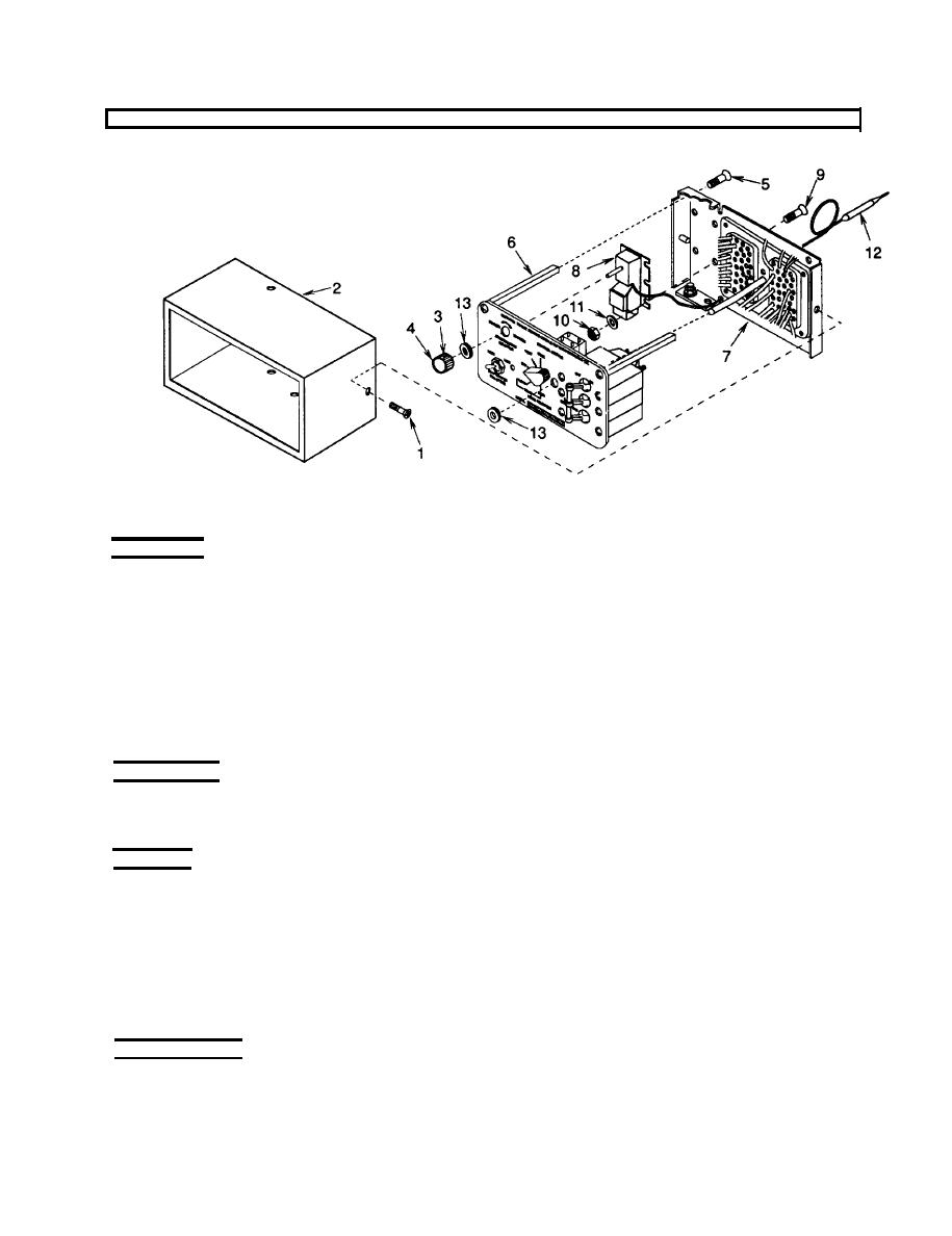
Figure 4-17. TEMPERATURE SELECTOR (Control Switch Thermostat) S3
REMOVAL
1. Remove four screws (1) and pull cover (2) off.
2. Loosen setscrew (3) in TEMPERATURE SELECTOR knob (4). Remove knob.
3. Remove three self-locking screws (5) from posts (6) and slip back plate (7) off.
4. Tag and disconnect wires from TEMPERATURE SELECTOR (8).
5. Remove four screws (9), flat washers (11), and self-locking nuts (10) and pull TEMPERATURE SELECTOR (8)
from back plate (7).
INSPECTION
Check TEMPERATURE SELECTOR (8) for kinked or damaged capillary line or bulb and loose, broken or
missing terminals.
TESTING
1.
Place the sensing bulb (12) in a container of warm water, 75 to 85F (24 to 30C) and set multimeter to
measure resistance on lowest scale. Place multimeter leads on terminals 1 and 3 of the thermostat (blue and
red). Turn the knob to the extreme cooler position. There should be no indication of continuity on multimeter.
Turn the knob to the extreme warmer position. Continuity should be indicated on the multimeter.
2.
Center or mid-range of the Temperature Selector represents a setting of about 75F (24C). With the sensing
bulb remaining in the container of warm water, 75 to 85F (24 to 30C), slowly turn the knob from the extreme
warmer position towards the cooler position. Continuity should cease before or near mid-range of the knob.
REPLACEMENT
Replace TEMPERATURE SELECTOR if defective.
4-63
