
TM9-4120-400-14
TIME DELAY RELAY (K1).
e. Installation
d. Replacement
c. Removal
b. Inspection
a. Testing
This task covers:
INITIAL SETUP
Equipment Condition
Tools
Remove junction box (para 4-27).
Refrigeration Unit Service Tool Kit
Appendix B, item 1
Power Supply
Appendix B, item 6
Materials/Parts
Time Delay Relay
Self-locking Nuts (2)
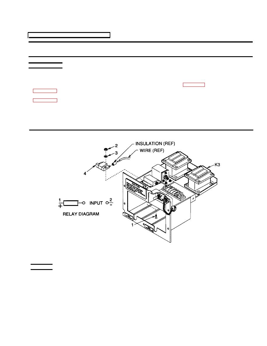
Figure 4-24. Time Delay Relay K1
TESTING
1.
Connect multimeter to terminal A1 and A2 of relay K3.
Apply +28VDC to terminal 6 of TB1 and -28VDC to terminal X2 of K3.
2.
3 seconds after applying the 28 VDC.
Multimeter must show continuity across terminals A1 and A2 within 30
3.
4.
Remove the 28VDC. The multimeter must show that contacts are open.
4-77
