
TM 9-4120-407-14
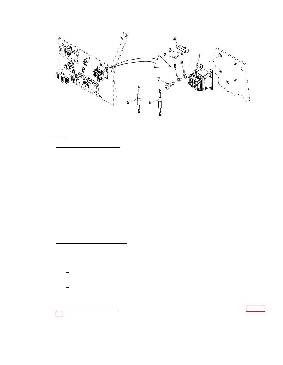
Figure 3-49. Relay (K2), Diode (CR3), and Surge Arrestor (SA1)
b. Testing.
(1) Relays (K1) and (K2) Testing. The following procedures apply to both relays and should be
performed on each one separately.
(a) Using power supply, apply 28 volts dc to relay coil terminals X1 and X2.
(b) Using multimeter set to measure resistance, check continuity in turn between relay contacts Al
to A2, B1 to B2, and C1 to C2. Continuity should be indicated.
(c) Disconnect power supply from relay coil terminals X1 and X2.
(d) Using multimeter set to measure resistance, check continuity in turn between relay contacts Al
to A2, B1 to B2, and C1 to C2. No continuity should be indicated.
(e) Replace relay if it is defective.
NOTE
Surge arrestor (SA1) protects rectifier (CR4). If the surge arrestor is
defective, it is advisable to test the rectifier.
(2) Diodes (CR2) and (CR3) Testing. The following procedures apply to both diodes and should be
performed on each one separately.
(a) Using multimeter set to measure resistance, check resistance across the diode per the following
procedures.
1 Connect black lead (negative) to terminal nearest the band on diode body and the red lead
(positive) to the opposite terminal. Slight resistance should be indicated.
2 Connect red lead (positive) to terminal nearest the band on diode body and the black lead
(negative) to the opposite terminal. No resistance should be indicated.
(b) Replace the diode if it is defective.
(3) Surge Arrestor (SA1) Testing. No conclusive test can be performed on the surge arrestor (6) Figure 3-
3-117
