TM 9-4120-407-14
4-7. LOGIC BOX ASSEMBLY TESTING AND REPLACEMENT. (Cont)
b. Removal.
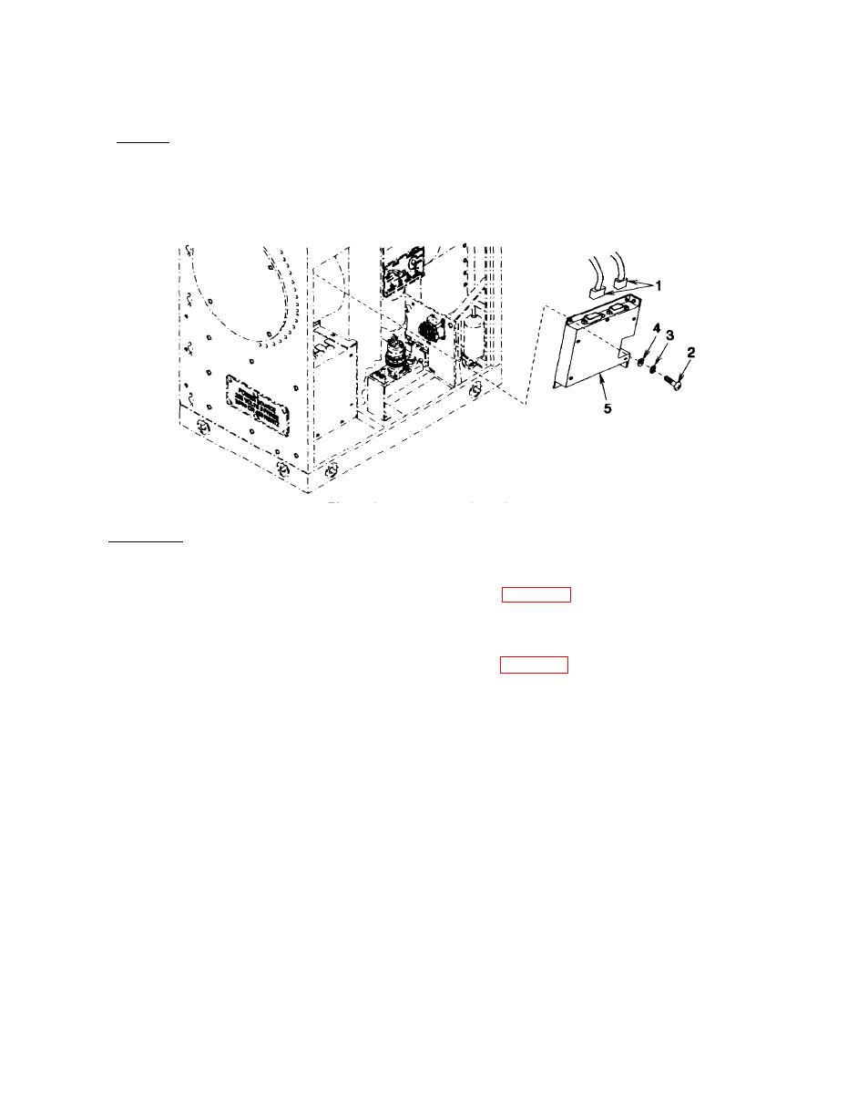
(1) Tag and disconnect cable connector (1)
(2) Remove two screws (2), lock washers (3), flat washers (4), and logic box assembly (5). Discard
lock washers.
Figure 4-2. Logic Box Assembly
c. lnstallation:
(1) Install logic box assembly (5), two screws (2), new lock washers (3) and flat washers (4).
(2) Connect cable connectors (1) per tags and wiring diagram Figure 3-5. Remove tags.
NOTE
FOLLOW-ON MAINTENANCE:
Install lower front cover panel. See para 3-14.
4-16

