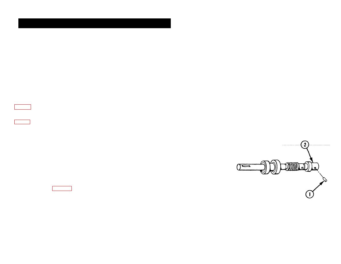
6-30. INPUT SHAFT ASSEMBLY-MAINTENANCE INSTRUCTIONS
TM 9-4910-387-14-2
THIS TASK COVERS:
a. Removal
d. Reassembly
b. Disassembly
e. Installation
c. Repair
INITIAL SETUP
Tools and Special Tools
for the counter pulse switch and tachometer generator assembly
General mechanic's automotive tool kit (5180-00-177-7033)
TM 94910-387-24P
References
Equipment Conditions
ter pulse switch and tachometer generator
Main power source to tester is turned off
assembly
4-32 Upper back panel is removed
4-33 RH upper side panel is removed
REMOVAL
DISASSEMBLY
NOTE
1 SPRING PIN (1). Remove
For removal instructions for
2 TACHOMETER GENERATOR
the input shaft assembly,
COUPLING (2). Remove.
refer
to
removal
and
disassembly procedures for
the counter pulse switch and
tachometer
generator
assembly, p 6-424.
6-456

