
(d) Turn the 40-ohm field current rheo-
s t a t (16) clockwise until 150 am-
peres are indicated on the load dc
a m m e t e r (1).
( 4 ) should be between 1.6 to 2.1
volts. A lower than the above volt-
age reading indicates a shorted
i n t e r p o l e and compensating wind-
ings; higher than above voltage
reading indicates high resistance in
t h e windings.
( f ) C h e c k the generator brushes for
sparking, and the generator for un-
usual noises and excessive heat.
( g ) Turn the 40 ohm field current rheo-
stat (16) in the fully counterclock-
wise direction and the speed control
h a n d l e (22) partially counterclock-
w i s e until the varidrive assembly
speed is reduced to speed. Stop
t h e varidrive assembly by depres-
sing the stop button (12-C) on the
d r i v e control (21).
6 above, in positions indicated in
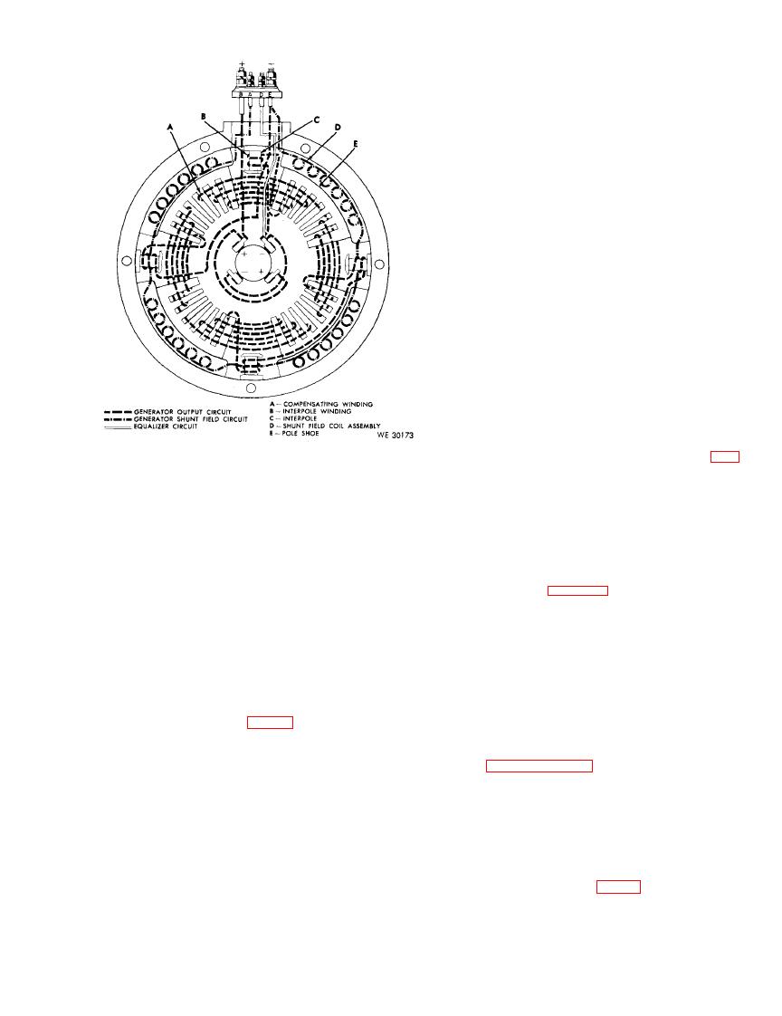
B e n d i x Eclipse Pioneer model EC30E00-3A
150-ampere generator.
column 3b of the table. Remove all
cables, leads, and the generator
handle (22) slowly clockwise until
from the test stand.
3,000 rpm are indicated on the
(i) P o l a r i z e the generator (par. 99d).
t a c h o m e t e r indicator meter (3).
Note. The key numbers shown below in parentheses in this section refer to figure 32 except where otherwise
indicated.
Section VI.
TESTING BENDIX ECLIPSE PIONEER 150-AMPERE
GENERATOR CONTROL BOX
at its maximum electrical capacity and/or con-
119. Description
trols the output of the generator within allow-
The Bendix Eclipse Pioneer 150-ampere
able limits preventing a burned-out generator.
generator control box (fig. 39) is designed for
T h e individual control units and components
use with a generator that has a current output
used in the construction of the control box are
of 150-amperes (par. 117). The control box is
l i s t e d in paragraph 120. Refer to TM 9-8631
c o m p o s e d of a series of control units which
f o r complete descriptive information.
function in unison to regulate the output volt-
age and limit output current of the generator.
120. 150-Ampere Generator Control Box
I t also automatically connects or disconnects
Control Units Test (Eclipse Pioneer)
the generator to or from the electrical system
a. Purpose. This
test is performed to indi-
dependent upon the need for, or ability of the
cate the functioning
of the control units of the
g e n e r a t o r to supply the electrical energy re-
150-ampere control
box (fig. 39) and whether
quirements, therefore, maintaining a sufficient
electrical output to keep the unit under charge
s e t t i n g adjustments
are required to the units
