TM 9-4935-481-14-1
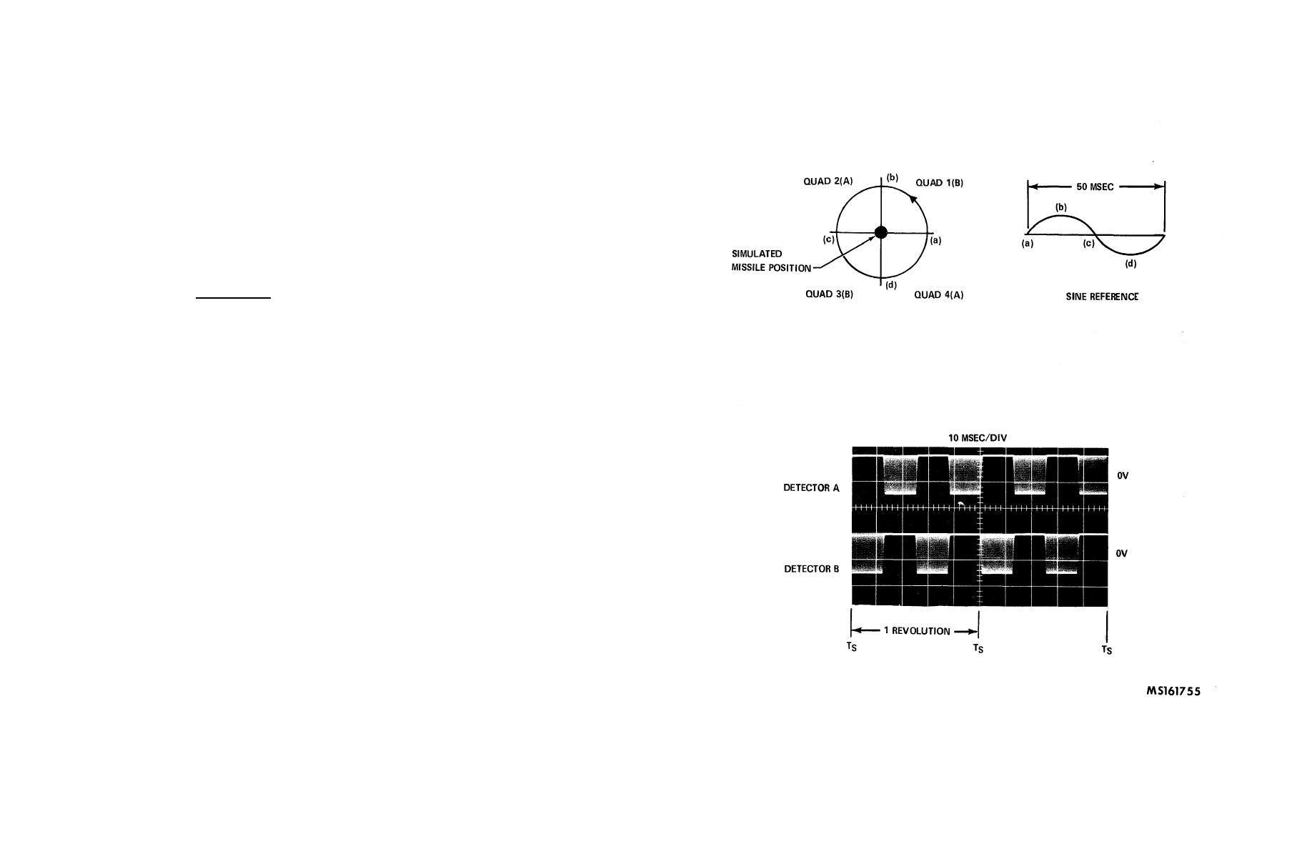
one-fourth of the total, or 12.5 msec. The detector output waveform shown begins at Ts with the 0 crossing of the sine wave,
so that the first output will be from quadrant 1 (detector B). As the circle travels ccw, it next enters quadrant 2 and the signal
is seen to originate from detector A while detector B goes to 0. Similar crossings occur as the circle enters quadrant 3 and
then 4, and then the next revolution begins.
(4) Controls. The detector simulator section contains the controls necessary to vary the modulation frequency,
the output amplitude, and the amount of horizontal and vertical error.
(a) Amplitude potentiometer, R3 is used in conjunction with the scale factor switch (S26) directly beneath
it. The CSCB is scaled to accept an RMS value of current from the detector, therefore the voltage output of the simulator
must first be passed through a 1 Mo resistor before it enters the tracker electronics. Accordingly, amplitude settings of the
simulator are calibrated in terms of current output, with S26 selecting a multiplier of X10-8 X10⁻⁹, or X10-10 amps. Maximum
output would be a dial setting of 9.99 and a multiplier setting of X108, to result in a current output of 9.99 X10⁻⁸ amps RMS.
-
The actual simulator output in volts peak-to-peak for this setting may be computed as follows:
Vpp x .5 x .7071 = 9.99 x 10⁻⁸
6
1.01 x 10
Vpp @ 286 mv
The value of resistance used in the calculation is 1.01 Mo, since the input impedance of the tracker electronics is 10 K .
W
(b) Frequency control R4 varies the modulation frequency from approximately 4.0 KHz to approximately
12.0 KHz. This range is sufficient to cover the trainer and tactical modes of tracker operation.
(c) To introduce horizontal or vertical errors into the simulator, offset potentiometers R1 and R2 are used.
Errors of either polarity may be selected by the switch under each offset control. Setting each switch to the zero position
would represent the boresight condition discussed in (B) and (C) above. The error controls are calibrated such that the
setting corresponds to the expected dc error output on the tracker rate/position signals. For example, a dial setting of 500
Figure 3-6. Detector simulator parameters, boresight condition
3-11


