TM9-4935-481-14-1
C3
Table 3-10. DMS-D Maintenance Calibration-Continued
Table 3-10. DMS-D Maintenance Calibration-Continued
STEP
UNIT
PROCEDURE
CORRECTIVE ACTION
STEP
UNIT
PROCEDURE
CORRECTIVE ACTION
NOTE
WARNING
Corrective action for steps for this procedure will be
accomplished by referring to the DMS-D performance test
Use extreme care when removing the front panel to
prevent injury to personnel or damage to equipment.
parentheses after each section sub-title or the DMS-D sche-
Place the aisle maintenance bench (see TM-02819D-15
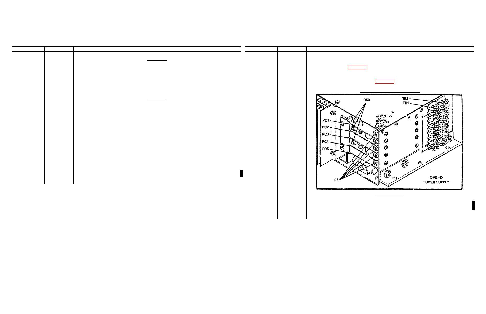
matics. Location diagrams for test points and potentiometers
or TM-06895A-15) in front of the DMS-D, and use it
can be found in figure 3-35 immediately following this
to support the front panel assembly when removed in
procedure.
the following steps
Power Supply Adjustments (1-14)
CAUTION
Insure the DMS-G is NOT cabled to the DMS-D.
NOTE
For this procedure, utilize 48" BNC - BNC cables
for the CT connections.
2
Remove the screws securing the front panel to the case and
remove the front panel assembly, rotating it approximately 90and
placing it on the aisle bench. Ensure that the cable harness
is not strained. Connect a GND between front panel and chassis.
NOTE
Ensure that all mechanical type dial adjustments on the
front panel are aligned at 000 at their fully ccw position
(see chapter 4 for adjustment procedure).
3
PP
DMS switch to ON.
4
MCP
DMM INPUT switch to DMM INPUT.
+5 VDC Supply
5
Monitor with the DMM pos probe at TB1-1.
6
PP
MAIN POWER switch to ON. Momentarily actuate Test Start switch.
TP
7
Adjust PC1-R50 several turns cw.
8
Adjust PC1-R3 fully cw.
3-60


