
TM 9-4120-411-14
4.35 TEMPERATURE SENSOR (RT5) REPLACEMENT.
THIS TASK COVERS
a. Removal
b. Installation
INITIAL SETUP:
Tools
Materials/Parts
General Mechanics Tool Kit
Marker Tags (qty 2)
Item 1, Section III, Appendix B
Item 3, Section II, Appendix E
Rivet Gun
Blind Rivets (qty 8)
Item 7, Section III, Appendix B
Item 6, Section II, Appendix E
Tiedown Straps (qty 2)
Item 2, Section II, Appendix E
Splices (qty 2)
Item 5, Section II, Appendix E
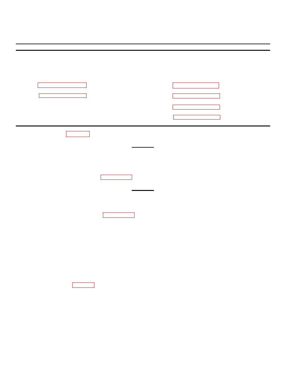
a. Removal. See figure 4-34.
WARNING
Rotating parts and lethal voltage levels are used in operating the FDECU. Be sure
power source is disconnected. Injury or death can occur if connected to power
source.
(1) Shutdown the FDECU per paragraph 2.4 and disconnect it from power source.
WARNING
The FDECU cover is heavy. Be sure the cover retaining rod is in place and
properly secured with hair pin cotter. Injury can occur if cover drops.
(2) Raise and secure cover per paragraph 4.2.
(3) Cut and remove tiedown strap (1) securing temperature sensor (2) leads. Discard tiedown strap.
(4) Tag the temperature sensor (2) leads at connection points then cut off and discard two splices (3) to
disconnect leads.
(5) Drill out eight blind rivets (4) using drill with drill bit slightly smaller than rivet diameter. Remove sensor
cover (5) and any remaining rivet material.
(6) Cut and remove tiedown strap (6) securing temperature sensor (2) then pull leads through hole in frame to
remove. Discard tiedown strap.
b. Installation. See figure 4-34.
(1) Carefully push temperature sensor (2) leads through hole in frame.
(2) Secure temperature sensor (2) in place with tiedown strap (6).
Cut to remove excess tiedown strap
material.
4-87

