
TM9-2330-207-14
Section VII. WHEELS, HUBS, AND DRUMS
Page
Page
Wheels
Overview
Description
Tires
Tire Pressure
Brake Drum and Hub
4-27. OVERVIEW
This section pertains to organizational maintenance of the semitrailers' wheels, hubs and brake drums.
Included are organizational maintenance procedures for tires and bearings.
a. General. The brake drums and wheels are mounted on the hubs. Each hub is mounted on the spindle
of its axle on two tapered roller bearings. The wheels are mounted on the hub with 10 wheel studs, cap nuts,
and wheel nuts. Cap nuts and wheel nuts on the right side of the semitrailer have right hand threads and are
marked "R". Those on the left side have left hand threads and are marked "L". Wheel nuts and cap nuts must
must be turned in the opposite direction to the normal rotation of the wheel to be loosened or removed. The
weight of the semitrailer and load is carried on two opposed tapered roller bearings in each hub. The bearing
cups are a press fit in the hubs. The bearing cones and roller assemblies are removable for cleaning, inspec-
tion, and lubrication. An adjusting nut with pin, a locking washer with holes to accommodate the pin of the
adjusting nut, and a jamnut secure the hub with bearings on the spindle. A grease seal and wiper are fitted
behind the inner bearing to protect the brake linings from lubricant.
b. Brake Drums.
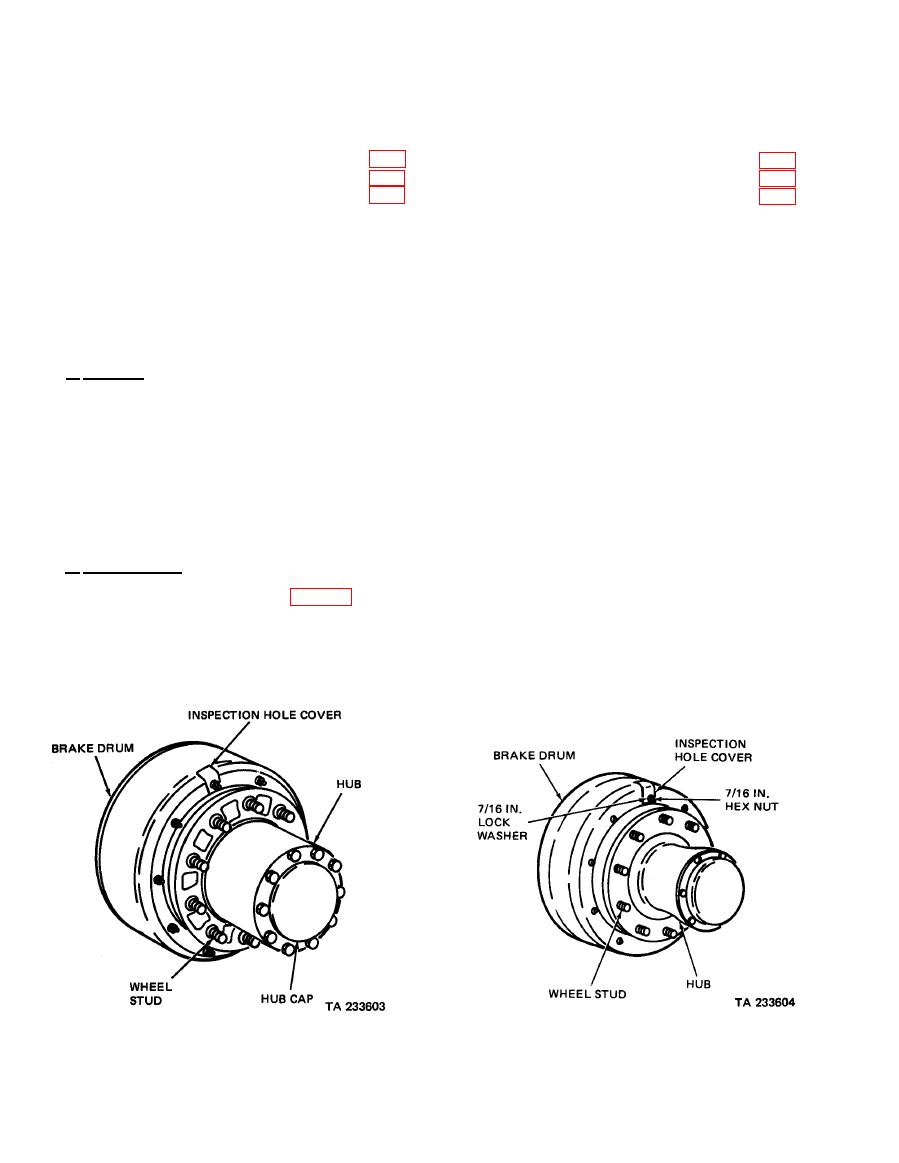
(1) M127. The brake drum (fig. 4-22) is attached to the hub through a dished brake drum adapter.
The adapter is secured to the hub by 10 cap screws and Iockwashers and to the drum by 10 bolts and lock-
nuts. These bolts also secure the oil slinger to the adapter and one of them retains the inspection hole cover.
The oil slinger is a metal plate with a hole in the center, which protects the brake lining from lubricant. The
inspection hole permits the brake lining clearance to be checked. A hub cap and gasket, fastened by 10 cap
screws and Iockwashers over the center of the hub, excludes moisture and foreign matter.
except M127)

