
TM 9-2330-388-14
1.
Lift water dispensing unit engine and pump into
front door. Slide and pivot assembly to line up with water
inlet.
2.
Install two bolts to connect coupler between "U"-
tube water outlet and pump inlet adaptor.
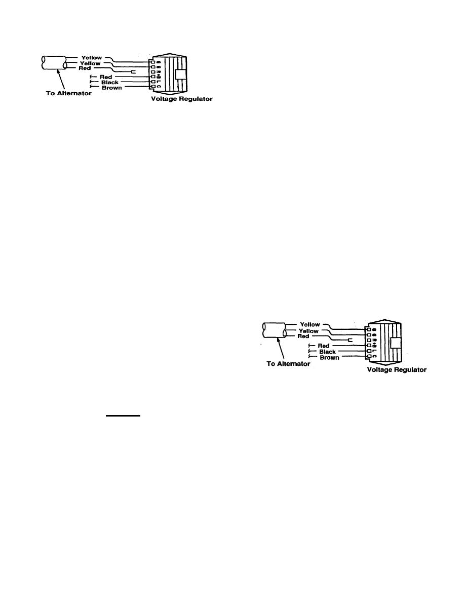
Figure 4-26. Voltage Regulator Harness
3.
Connect discharge valve to pump outlet by
4.
Disconnect upper red
alternator-to-voltage
securing coupler with two bolts.
regulator wire at voltage regulator.
4.
Connect skid to mounting plate with four bolts
5.
Disconnect first negative, then positive battery
and washers.
cab from battery.
5.
Install one fuel supply line and two return feed
6.
Remove battery hold-down brace by removing
lines at tank.
nut and washer from each of two studs.
6.
Install battery, carefully observing that negative
7.
Remove battery.
terminal is to front.
8.
Tag and disconnect one fuel line and two return
7.
Install battery hold-down brace and secure with
lines from engine. Plug tank and lines. Mark hoses for
nut and washer at each of two studs.
identification and pull out of way.
CAUTION
9.
Drain oil from engine.
Make sure red wire Into the "R" terminal at
10.
Disconnect skid from mounting plate by
regulator Is disconnected before connecting
removing: four nuts and washers from bolts attaching
battery. Then re-connect the red wire after
engine/pump assembly to engine compartment floor.
battery is connected and before operating
unit.
11.
Remove two bolts and coupler that holds pump
outlet and discharge valve. Separate from pump.
12.
Disconnect and remove coupler between "U"-
tube water outlet and pump inlet adaptor.
13.
Slide water dispensing unit engine and pump
assembly out front door of cabinet by pivoting around
water outlet and lifting unit out.
Figure 4-27. Voltage Regulator Harness
b.
Installation
8.
Connect battery cables, first positive and then
negative, carefully observing polarity. Positive cable
CAUTION
goes to connection at starter.
Observe correct polarity when connecting
9.
Connect
upper
red
alternator-to-voltage
the battery cables: positive cable to positive
regulator wire at voltage regulator.
post and negative to negative. If cables are
10.
Fill engine with oil.
reversed, even momentarily, the voltage
regulator and alternator will be damaged
11.
Install rear panel on cabinet with six screws.
immediately and must be replaced.
12.
Open emergency valve and discharge valve and
A loose or intermittent ground connection
let unit discharge until stream runs normal.
between battery negative terminal and volt-
age regulator frame will cause a varying
charge current and damage to the voltage
regulator may occur.
4-89

