
TM 9-3405-215-14&P
BAND FILING
Machine Set-Up:
Before internal or external filing may begin:
(1) Remove saw band, table center disk, post band
guard, and saw guides. Mount file guide support to
lower keeper block. Make sure proper file band slot
width is used. See Fig. 43.
(2) Lower upper post to proper work thickness. This
should not exceed 2 inches (50 mm) for 1/4-inch
(6.4 mm) band, 4 inches (10 mm) for either 3/8-inch
(9.5 mm) or 1/2-inch (12.5 mm) bands. Longer
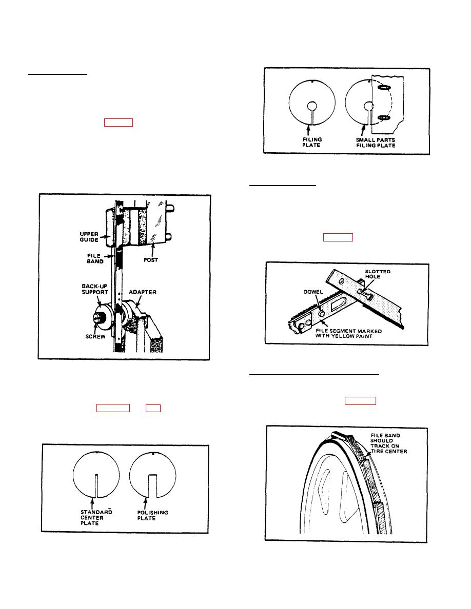
FIG. 45. SPECIAL TABLE CENTER FILING PLATES
guides that permit greater thickness filing are
available as accessories.
File Band Joining:
Place one band end in each hand. Hold yellow painted
end in left hand. Depress spring steel band tip in right
hand with yellow segment lock rivet in left hand. Slip
rivot head into slotted hole. Slide rivet head into slot's
small end. Straighten band. Allow spring steel end to
snap over dowel. See Fig. 46. Band ends must be flush
before operating.
FIG. 46. JOINING THE FILE BAND.
File Band Tracking and Tensioning:
FIG. 43. FILE GUIDE INSTALLATION.
Align band on wheels in same manner as for saw band
(3) Install upper file guide and lock it firmly to post with
tracking. Tilt upper wheel, if necessary, to make band
knurled thumb screws. install special table center
run on wheel crown. See Fig. 47. Band should run
freely over file guide supports when properly tracked.
end through table center disk. File cutting edges
should face downward.
FIG. 44. STANDARD TABLE CENTER PLATE AND
POLISHING PLATE
FIG. 47. FILE BAND TRACKING.
24

