
TM 9-4120-370-14
TO 35E9-229-1
The following test must be conducted with the power on. Use extreme caution.
Do not connect P1 connector to air conditioner before making following checks.
h.
Connect power cable to a power source of 208 volt, 3 phase, 400 hertz for models F36T4-2S, F36T4-2SA, and
F36T4-2SB, or 50/60 hertz for models F36T-2S and F36T-2SA. (See Figure 4-12 and 4-22.)
(1)
Apply power to power cable.
(2)
Use a multimeter set to AC voltage range of at least 250 volts for following tests.
Measure voltage between pin D of connector PI and a good chassis ground. Voltage must be zero (0).
(3)
If more than zero voltage is observed, disconnect cable and check power source. Correct problem at power
source or at cable connection as indicated.
(4)
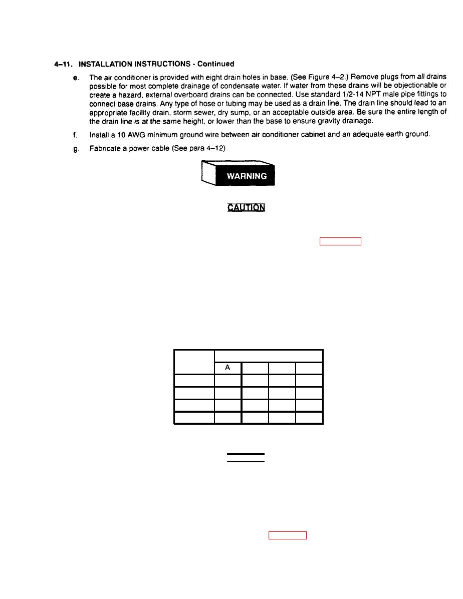
With zero voltage on pin D of P1 connector, check voltages between remaining pins as shown on following
chart.
PI CONNECTOR
Measure
To Pin
from pin
B
C
D
120
208
A
N/A
208
N/A
B
208
208
120
120
208
N/A
208
c
120
120
N/A
D
120
Voltage should be approximately as shown. If voltages are not within ten volts of those indicated on chart, disconnect
power. Locate and correct problem.
CAUTION
Check that mode selector switch is OFF.
(5) After proper voltages are indicated on all pins of connector PI. connect P1, to connector J1 on air
conditioner.
NOTE
The following steps require two people. One must be at control panel. The other must
be in position at rear of air conditioner to see condenser fan rotation. (Condenser fans
can be seen through condenser air outlet grilles, Figure 1-2, item 2.)
4-17

