
TM 9-2330-211-14&P
4-18. RECEPTACLE (Con't)
ACTION
ITEM
REMARKS
LOCATION
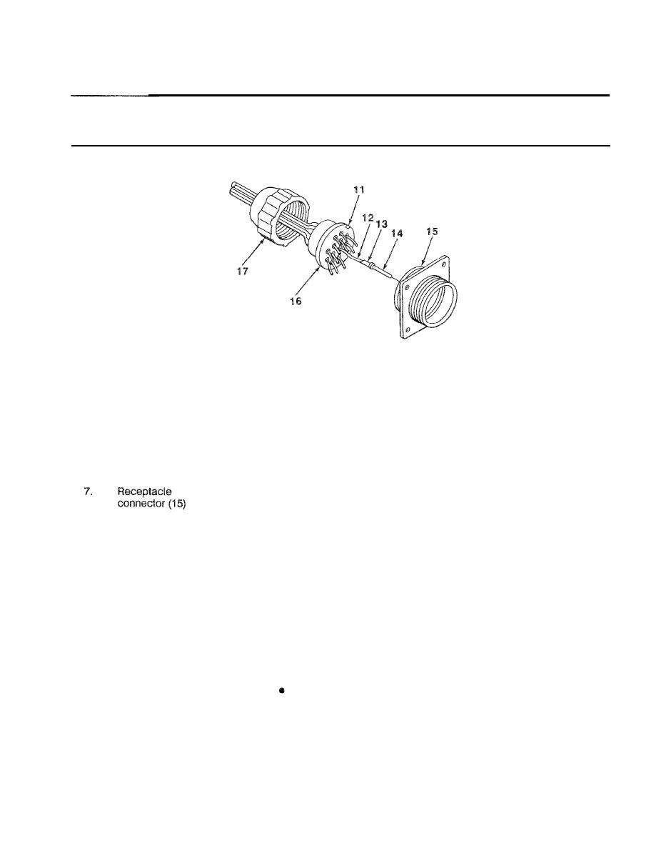
5 . Bushing (16)
Defective contact
a.
Using pliers, pull contact pin (14) out of bushing
pin (14)
(16).
b.
remove from wire (12).
6.
Wire (12)
Replacement
a
Place solder well (13) onto wire (12) and solder
contact pin (14)
using soldering tool.
b.
Push solder well (13) into bushing (16) until
seated.
Bushing (16)
Push bushing (16) into receptacle connector (15).
Ensure that notch (11) is alined with
receptacle connector (15).
8.
Nut (17)
Screw nut (17) onto receptacle connector (15).
INSTALLATION
9.
Front of
Push wiring harness (10) back into center hole
Cover (6) and
semitrailer
receptacle
(9) and aline screw holes.
Ensure that notch (4) is at top.
assembly (7)
Four screws (5),
10.
Cover (6) and
Screw in and tighten using screwdriver, socket
receptacle
ground wire (3),
extension, and handle.
assembly (7) to
Iockwashers (2),
screw holes
and nuts (1)
FOLLOW-ON MAINTENANCE:
Check operation of lights.
TASK ENDS HERE
4-47
