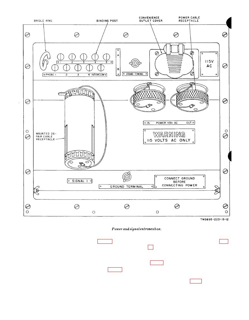
Figure 8.
13 and
2 0 ) . The teletypewriter patch panel
provides
The power cable assembly is
a means of connecting the cords of
the TT-
wound on a reel, which is secured to
4A(*)/TG's and the TT-76(*)/GGC
to the
the floor at the front of the shelter
teletypewriter circuits.
3-conductor cable with a watertight
h. TH-5/TG Subdistribution Panel (fig. 12
power connector on each end.
and 21). The panel distributes and controls
ac power to the TM-5/TG's.
i. Cords and Cables.
cable stub is a 15-foot, 3-conductor

