TM 55-1925-283-12&P
0014 00
2
1
4
5
3
6
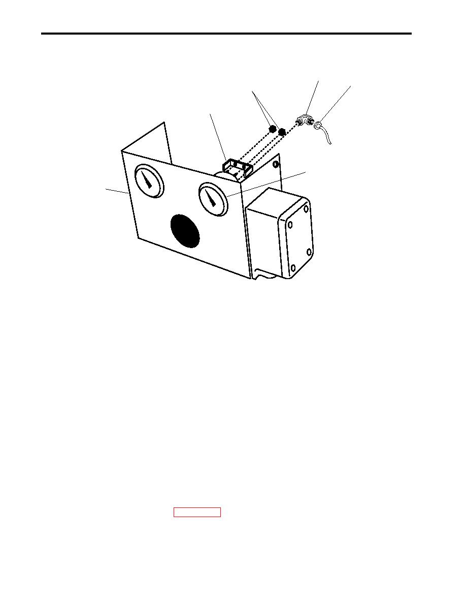
Figure 4. Gauge Replacement
INSTALLATION
1. Position the gauge (figure 4, item 3) in the indicator panel (figure 4, item 6) and secure it with the retaining
clamp (figure 4, item 5) and two retaining nuts (figure 4, item 4).
2. Wrap the male pipe threads of the elbow (figure 4, item 2) with antiseizing tape and install the elbow into the
gauge (figure 4, item 3).
3. Install the gauge line (figure 4, item 1) on the elbow (figure 4, item 2).
4. Position the indicator panel (figure 3, item 4) on the fuel filter/water separator and secure it with the four
screws (figure 3, item 3).
5. Install the discharge pressure gauge line (figure 3, item 1) on the elbow (figure 3, item 2).
6. Repeat step 5 above for the inlet pressure gauge line.
7. Prime the fuel filter/water separator (WP 0005 00) and return it to the desired readiness condition.
0014 00-6


