
TM 55-1925-284-14&P
0029 00
Table 1. Normal Clearances for URA1 22 Blowers (Refer to Figure 3)
Frame
Impeller Ends
Cylinder
Impeller
Size
Total
Drive End
Gear End
Inlet and
Center
Fronts/Backs
Minimum
Minimum
Discharge
Center
22
.006/.010 in
.003 in
.003 in
.004/.005 in
.002/.003 in
.007/.01 in
(.15-.25 mm)
(.08 mm)
(.08 mm)
(.10-.13 mm)
(.05-.08 mm)
(.18-.25 mm)
30. Install the gear nut (figure 1, item 15) on the drive shaft (figure 1, item 4) and tighten slightly.
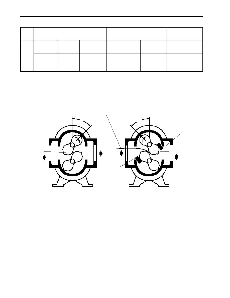
31. Check the impeller (figure 1, item 13) fronts and backs clearances at each 45 degree position as indicated in
table 1 and figure 3.
FEELER
GAUGE
45O
45O
WEDGE
BACKS
FRONTS
WEDGE
Figure 3. Impeller Fronts and Backs Clearances
32. The clearance for the impeller (figure 1, item 13) fronts and backs should be about the same and within the
specified range of table 1. Adjust the gear (figure 1, item 16) as necessary to obtain the required clearances.
Once the clearance is obtained, continue with the procedure. If the proper clearance cannot be obtained, a
new blower is required.
33. Wedge the impellers (figure 2, item 1) with blocks of hardwood (figure 2, item 2) to keep them from turning
during assembly.
34. Torque the drive gear nut (figure 1, item 15) to 60 lb-ft (81.3 Nm).
35. Remove the hardwood (figure 2, item 2) from the impellers (figure 2, item 1).
0029 00-8
