TM 55-1925-284-14&P
0029 00
36. Rotate the drive shafts (figure 1, item 4) by hand to ensure that there are no gear (figure 1, item 16)
tight spots or impeller (figure 1, item 13) contacts. If there are tight spots or impeller contact, loosen
the gear nut (figure 1, item 15) and perform steps 27 through 36 until there are no tight spots or impeller
contact. If there are no tight spots or impeller contact, continue with the procedure.
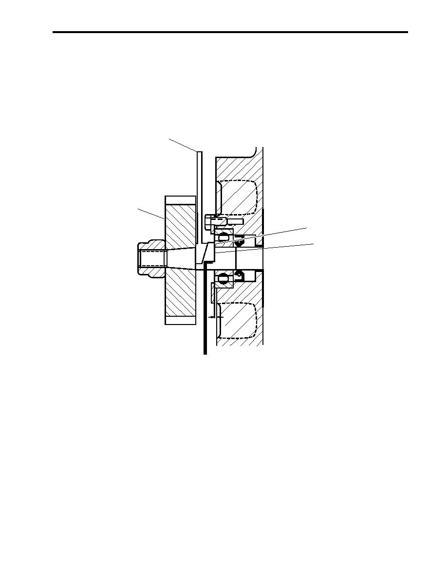
37. Adjust the thrust for the impeller (figure 1, item 13) by placing the flat side of the thrust adjuster saddle
(figure 4, item 1) against the bearing's inner race (figure 4, item 2) and the flat side of the thrust
adjuster fork (figure 4 item 3) against the back side of the gear (figure 4, item 4).
3
4
2
1
Figure 4. Impeller Thrust Adjustment
38. Install a 0.003 inch (0.8 mm) feeler gauge between the impeller (figure 1, item 13) and the gear end head
plate (figure 1, item 9). Tap on the top of the thrust adjuster fork (figure 4, item 3) until the feeler gauge
becomes snug.
39. Remove the feeler gauge and check end clearances. To increase the gear end clearance, tap the gear end
of the drive shafts (figure 1, item 4) with a brass hammer.
40. Check the end clearances between the impellers (figure 1, item 13) and the drive end head plate (figure 1,
item 21). If necessary, repeat steps 37 through 39 to adjust the drive end head plate clearance.
41. Pack the bearing cavities (figure 1, items 28, 31, and 34) with general purpose grease.
42. Install the new bearing cover (figure 1, item 30) in the drive end head plate (figure 1, item 21) using an arbor
press. Drive the bearing cover into the bore until it is flush with surface of the drive end head plate.
0029 00-9

