
TM 55-1925-285-13&P
0003 00
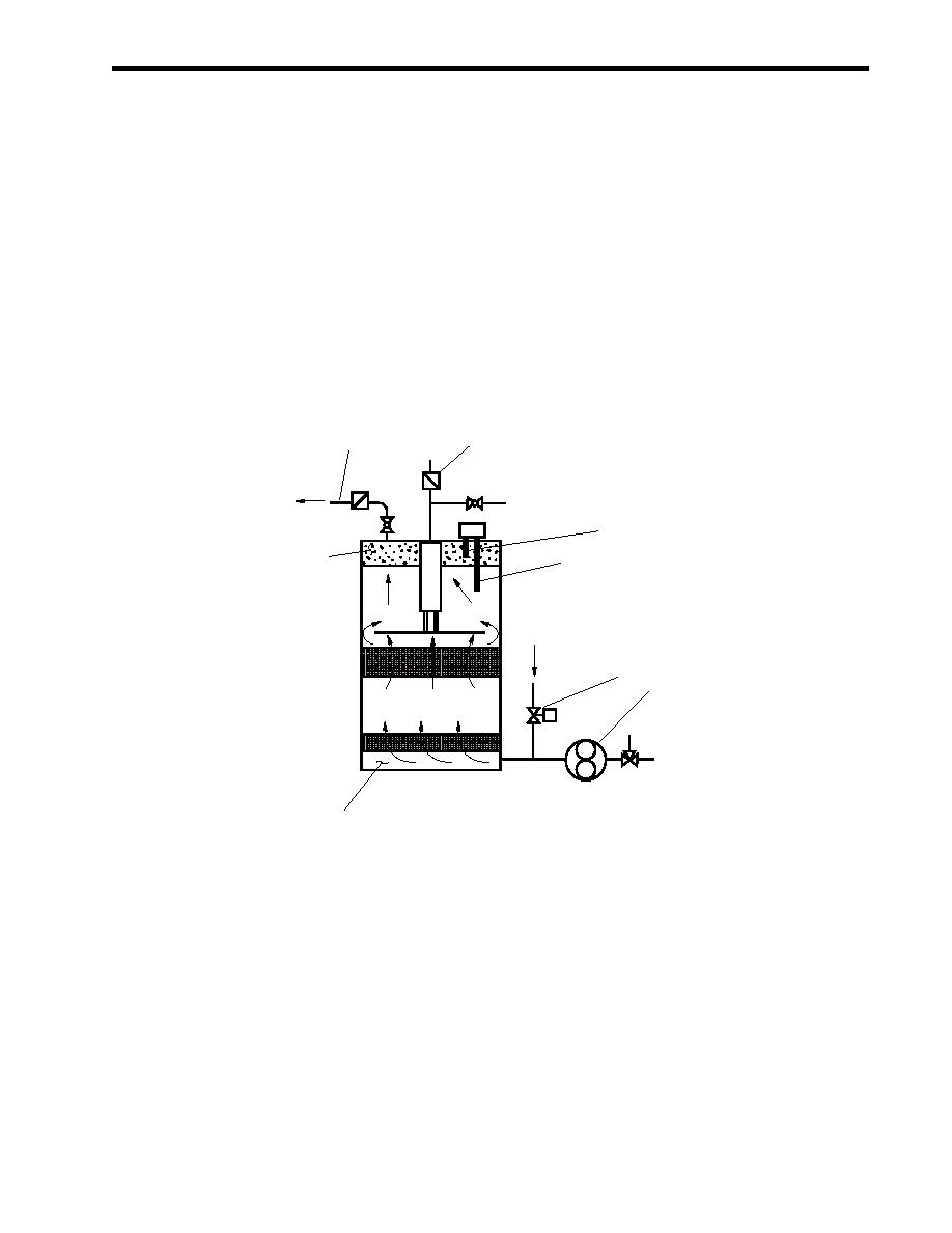
OIL DISCHARGE
The OWS contains an oil-water interface sensor mounted in the top of the tank. The sensor has two probes,
each a different length. An electrical current flows between the probes and the tank wall, and the control unit
measures the conductivity of the surrounding fluid. Water is highly conductive, while oil and air are not. There-
fore, when the tank is full of water, the control unit will sense the high conductivity. When enough oil has accumu-
lated to cover the lower probe tip (figure 2, item 1) (approximately 8-1/2 gallons (32.2 L)), the control unit will
sense the drop in conductivity and cause the OWS to enter oil discharge mode. At this point, the red OIL
DISCHARGE indicator on the control panel will illuminate. In the oil discharge mode, the OWS pump (figure 2,
item 2) stops, and the backflush inlet solenoid valve (figure 2, item 3) opens to apply seawater pressure (reduced
to 12 PSI (0.9 bar)) to the OWS tank. Seawater then enters the tank bottom (figure 2, item 4), backflushing the
coalescer beds and displacing the accumulated oil in the upper tank zone. A check valve (figure 2, item 5)
prevents back-flow through the inlet suction line. The oil is thus forced out through the oil discharge line (figure 2,
item 6) and into the OWT. Once the oil is discharged and the displacing water contacts the upper interface probe
(figure 2, item 7), the backflush valve will close, and the pump will start, resuming the normal processing mode.
5
6
OB-13
OIL TO
CLOSED
OWT
INTERFACE
OWS-2
7
SENSOR
OPEN
OIL
1
SEAWATER FROM
GENERAL SERVICE
SYSTEM
3
2
OWS
PUMP
4
OFF
Figure 2. Oil Discharge Mode
OIL CONTENT MONITOR (OCM)
The OCM controls a diverter solenoid valve on the OWS discharge to prevent the overboard discharge of any
effluent that has an oil content exceeding the selected limit. The OCM system automatically samples the effluent
from the OWS discharge pipe (figure 1, item 5) by way of a nozzle sampler whenever the OWS is operating. The
OCM analyzes the sample for oil content, activates alarms, and provides valve control signals to prevent unac-
ceptable effluent from being discharged overboard.
The OCM system is comprised of the sampling/sensor assembly (figure 3, item 1), remote indicator (alarm)
assembly (figure 3, item 2), and the remote relay assembly (figure 3, item 3). These three components are
electrically interconnected to function as follows:
0003 00-3
