0003 00
TM 55-1925-285-13&P
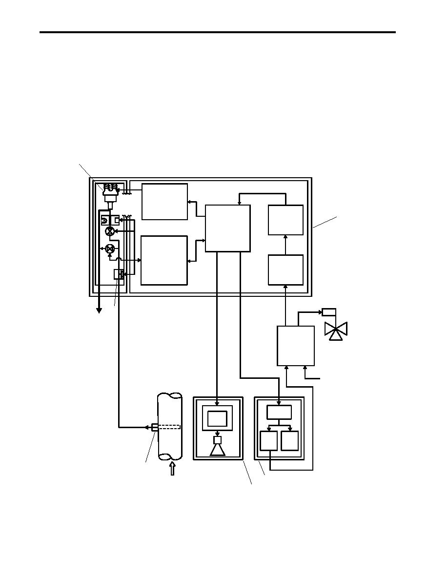
1. The sampling/sensor assembly (figure 3, item 1) samples the OWS effluent, measures the oil content, and
generates electrical signals for the system indicators, alarms, and control relays.
2. The remote indicator (alarm) assembly (figure 3, item 2) is the remote control and indicator unit for the OCM
system.
3. The remote relay assembly (figure 3, item 3) is the relay control link between the OCM and the diverter
solenoid valve on the OWS discharge piping. The diverter solenoid valve directs the effluent either over-
board or to the Oily Waste Tank (OWT).
5
SAMPLING/SENSOR ASSEMBLY
GENERATOR PCB
ULTRASONIC
VIBRATOR
TUBIDIMETER
ISOLATION
1
POWER PCB
SV1
SV2
PROCESSOR PCB
NOISE FILTER
PRESS
SW
6
S
DRAIN
ELECTRICAL
JUNCTION BOX
115 VAC
3-PH 50 HZ INPUT
REMOTE
RELAY ASSY
TIMER
DISPLAY
WINDOW
RELAY
RELAY
R1
R2
BUZZER
(AUX)
4
3
FLOW
2
Figure 3. Oil Content Monitor System, Block Diagram
0003 00-4


