
TM 55-1925-286-13&P
0019 00
3
L2
T2
T1
L1
2
1
4
7
5
6
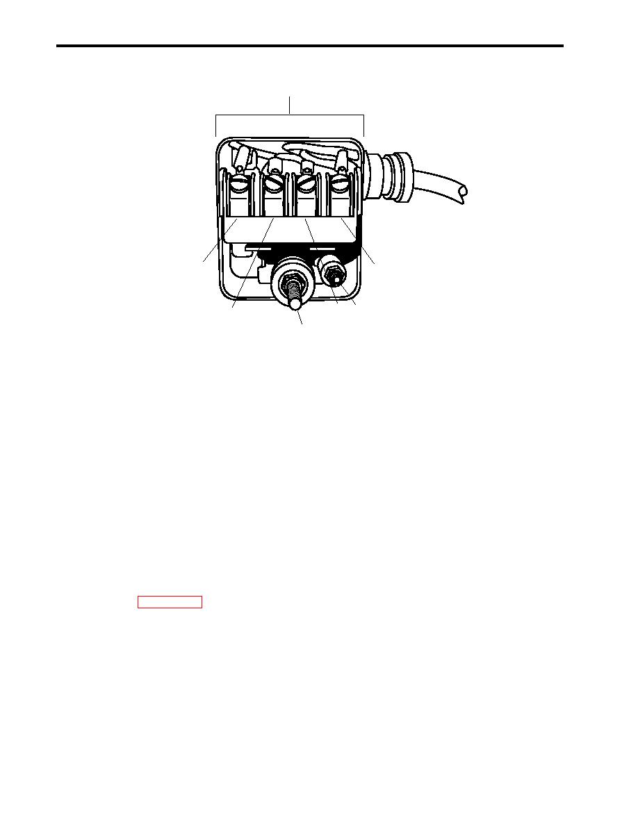
Figure 3. Pressure Switch
INSTALLATION
1. Position the pressure switch (figure 1, item 13) on the compressor foundation (figure 1, item 9), and secure
it with the two bolts (figure 1, item 14).
2. If a jumper wire is not already installed between terminals T1 (figure 3, item 4) and T2 (figure 3, item 5), in-
stall one.
3. Install the wiring into the pressure switch (figure 3, item 3), then connect the wiring to terminals L1 (figure 3,
item 1) and L2 (figure 3, item 2), using the labels from step 3 of Removal as a guide. Remove the labels.
4.
Adjust and test the pressure switch as follows:
a. Remove the lockouts and tagouts (FM 55-502) and return the air compressor to the normal operating
condition (WP 0005 00).
b. If the compressors are not running, drain air from the starting air receivers by opening valves CA-46 and
CA-47 STG AIR TK DR until the starting air pressure is below the cut-in pressure of 210 PSI (14.5 bar) to
permit the compressors to start. Close the valves when the compressors start.
c.
If the compressor does not start running when the pressure reaches 210 PSI (14.5 bar), adjust the cut-
in pressure. To adjust the cut-in pressure, turn the spring loaded adjusting screw (figure 3, item 6)
clockwise until the desired cut-in pressure is achieved. To decrease the cut-in pressure, turn the spring
loaded adjusting screw counterclockwise until the desired cut-in pressure is achieved.
d. Observe the compressors as they fill the receivers. The compressors should stop running when the
starting air pressure reaches the cutout pressure of 250 PSI (17.2 bar).
0019 00-4
