
TM 9-1375-213-12
(3) Look through, or insert a nail or wire into,
safety strip is withdrawn. Calculations must be
the inspection hole to ensure that firing pin has not
made accordingly.
been released. If firing pin has been released, nail
(3) Areas where explosives fuzed with this type
cannot be pushed through. Examine copper half of
of device have been installed and actuated should be
firing device tube to see that it is not dented and that
especially so marked and recorded. Troops must not
there is no evidence that glass ampoule of corrosive
approach installed charges employing this type of
chemical has been crushed.
delay firing device.
(4) Remove celluloid protective shipping cap
b. Preparation for Use (para 1-17b).
from coupling base and crimp on a nonelectric
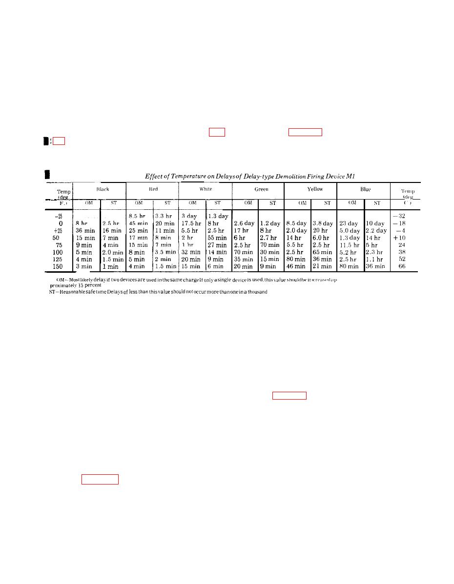
(1) Card found in each box of devices indicates
blasting cap (fig. 2-35). Crimper jaws should be
color for delay times at prevailing temperature (table
placed no further than inch from open end of
(2) Select firing device with strip of color
blasting cap.
corresponding to desired delay.
device is less than 2 hours. When delay is more
(5) Secure firing device in demolition charge or
than 2 hours, wait at least twice the time before
explosive device.
approaching.
(6) Crush ampoule between thumb and fingers.
(3) Unless it can be positively observed that
(7)
firing device's striker (firing pin) has functioned, do
WARNING
not handle misfired device. Detonate by placing a 1-
If safety strip does not remove easily, do not
pound demolition charge on top of or next to misfired
force it. Remove device from charge and
charge.
discard without removing safety strip. Firing
pin could be released by the handling
required to remove a jammed strip.
M1 and M1A
Remove safety strip.
(8) If firing pin has not been released, withdraw
a. Preparation for Use.
strip.
(1) Inspection before use. C h e c k f i r i n g
c. Misfires.
mechanism as follows:
(1) Exercise special care since firing device may
(a) Unscrew coupling base from firing
be mechanically jammed and can fire if disturbed
mechanism and inspect primer. Invert coupling base
when in this condition.
and hold it against firing mechanism, with nipple
(2) Delay type devices tend to have longer
extending into threaded end of firing mechanism.
delays as they age. Always allow at least twice
(b) Holding coupling base firmly against
anticipated functioning time at operating tem-
case, remove safety fork and safety pin. Depress
perature (table 2-5), plus half an hour, before ap-
proaching suspected misfire when nominal delay of
Change 2 2-33
