TM 9-2320-360-10
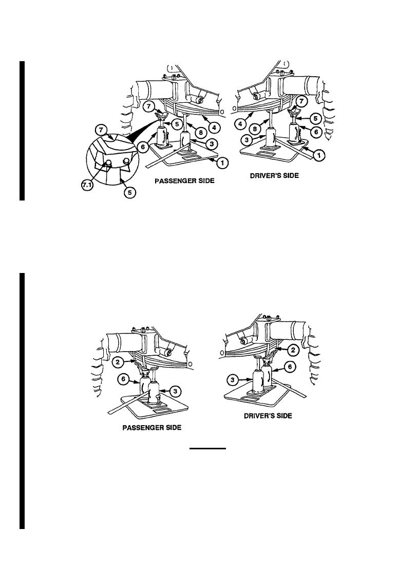
(3) Unscrew ram (8) of jack no. 1 (3) until touches spring (4).
(4) Unscrew ram (5) jack no. 2 (6) approximately 3 in. (7.62 cm.
NOTE
Adapter must be centered on jack.
(4.1) Install adapter (7) on ram (5) of jack no. 2 (6) with two locking pins (7.1) and position jack
on jack plate (1).
(4.2) Raise jack no. 1 (3) to its maximum height.
WARNING
Jack must be positioned using only the extension handle (Item 17.1,
Appendix ). Do not attempt to crawl under the vehicle to position
jack. Failure to comply may result in injury to personnel.
(4.3) Move jack no. 2 (6) directly under spring saddle (2).
(4.4) Raise jack no. 2 (6) until jack no. 1 (3) can be removed.
(4.5) Move jack no. 1(3) clear of the spring saddle (2) and spring (4) and go to step (4.13).
3-52 Change 1

