
TM9-2330-207-14
(b) When brakes are applied, each wheel cylinder's piston applies equal force against the toe and
heel of each brake shoe. As the brake shoe linings come into contact with the brake drum,
self-energization develops. Rotation of the brake drum pulls the brake shoe against the brake
drum's surface to augment the hydraulic force acting on the brake shoes to produce additional
braking action.
(c) The brake shoes are of the floating type, each being held in position by a brake shoe guide
pin, plain washer, C-washer, and two retracting springs. Each short retracting spring is hooked
to the anchor end of the brake shoe and to a projection on the brake shoe anchor pin. Each
long retracting spring is hooked to an anchor support at one end and the center portions of
a brake shoe at the opposite end.
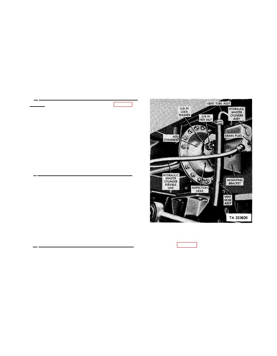
e. Hydraulic Master Cylinder (All Models Except
M127). The hydraulic master cylinders (fig. 4-38)
are installed and secured with the two air chambers
to mounting brackets secured to chassis frame
cross-members. Movement within the air chamber
causes a corresponding movement of a piston in
the hydraulic master cylinder. This movement
causes hydraulic fluid in the hydraulic master
cylinder to be put under pressure and forced
into the wheel cylinders for a brake application.
A filler cap is provided at the top of the hydrau-
lic master cylinder's body for use when filling
the cylinder with hydraulic fluid.
f. Wheel Cylinders (All ModeIs Except M127).
The wheel cylinders (fiq. 4-37) are self-centering
The wheel cylinder components include a piston
return spring, piston cups, long and short pistons,
and boots. The piston which actuates the toes of
the brake shoes has a longer cylinder bore than the
shorter piston in order to compensate for greater
movement of the shoe toe resulting from brake
adjustment for wear of Iining. The bleeder screw
and inlet ports are offset in the cylinder, toward
the short piston end.
(All Models except M127)
g. Hydraulic Lines (All Models Except M127). The hydraulic lines (fig. 4-35) consist of two flexible
lines and two rigid lines. The two flexible lines connect between each hydraulic master cylinder and a rigid
hydraulic line mounted on each axle. A rigid line, with a tee in the center for connection to the flexible line
is mounted on each of the axles. These rigid lines transmit hydraulic fluid to each internal brake assembly.
